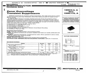
S8MC Green 8.0A SURFACE MOUNT GLASS PASSIVATED RECTIFIER Features Mechanical Data * * * * * * * * Glass Passivated Die Construction Low Forward Voltage Drop and High Current Capability Surge Overload Rating to 200A Peak Ideally Suited for Automated Assembly Lead Free Finish/RoHS Compliant (Note 1) Green Molding Compound (No Halogen and Antimony) (Note 2) * * * * * * Bottom View Top View Maximum Ratings Case: SMC Case Material: Molded Plastic. UL Flammability Classification Rating 94V-0 Moisture Sensitivity: Level 1 per J-STD-020D Terminals: Lead Free Plating (Matte Tin Finish). Solderable per MIL-STD-202, Method 208 Polarity: Cathode Band or Cathode Notch Marking Information: See Page 2 Ordering Information: See Page 2 Weight: 0.21 grams (approximate) @TA = 25C unless otherwise specified Single phase, half wave, 60Hz, resistive or inductive load. For capacitance load, derate current by 20%. Characteristic Peak Repetitive Reverse Voltage Working Peak Reverse Voltage DC Blocking Voltage Symbol VRRM
 4 Pages, 98 KB, Original
S8MC Taiwan Semiconductor CREAT BY ART 8A, 400V - 1000V Surface Mount Glass Passivated Rectifiers FEATURES - Low forward voltage drop - Ideal for automated placement - High surge current capability - Compliant to RoHS Directive 2011/65/EU and in accordance to WEEE 2002/96/EC - Halogen-free according to IEC 61249-2-21 definition MECHANICAL DATA Case: DO-214AB (SMC) DO-214AB (SMC) Molding compound, UL flammability classification rating 94V-0 Moisture sensitivity: level 1, per J-STD-020 Packing code with suffix "G" means green compound (halogen-free) Terminal: Matte tin plated leads, solderable per JESD22-B102 Meet JESD 201 class 1A whisker test Polarity: Indicated by cathode band Weight: 0.27 g (approximately) MAXIMUM RATINGS AND ELECTRICAL CHARACTERSTICS (TA=25C unless otherwise noted) PARAMETER SYMBOL S8GC S8JC S8KC S8MC Unit Maximum repetitive peak reverse voltage VRRM 400 600 800 1000 V Maximum RMS voltage VRMS 280 420 560 700 V Maximum DC blocking voltage VDC 400 600 800 1000 V Ma
 4 Pages, 228 KB, Original
S8MC Green 8.0A SURFACE MOUNT GLASS PASSIVATED RECTIFIER Product Summary @TA = +25C Features and Benefits VRRM (V) IO (A) VF (V) IR (A) 800, 1000 8 0.985 10 Glass Passivated Die Construction Low Forward Voltage Drop and High Current Capability Surge Overload Rating to 200A Peak Ideally Suited for Automated Assembly Lead Free Finish/RoHS Compliant (Note 1 & 2) Halogen and Antimony Free. "Green" Device (Note 3) Description and Applications Mechanical Data 8.0 A Surface Mount Glass Passivated Rectifier in SMC package, offers high current capability and low forward voltage drop, designed with Guard Ring for Transient Protection and high surge capacity. Top View Ordering Information Case: SMC Case Material: Molded Plastic. UL Flammability Classification Rating 94V-0 Moisture Sensitivity: Level 1 per J-STD-020D Terminals: Lead Free Plating (Matte Tin Finish). Solderable per MIL-STD-202, Method 208 Polarity: Cathode Band or Cathode Notch Marking Information: See Page 2 Ordering Information: See Page 2 W
 4 Pages, 271 KB, Original
S8MC Green 8.0A SURFACE MOUNT GLASS PASSIVATED RECTIFIER Product Summary @TA = +25C Features and Benefits VRRM (V) IO (A) VF (V) IR (A) 800, 1000 8 0.985 10 Glass Passivated Die Construction Low Forward Voltage Drop and High Current Capability Surge Overload Rating to 200A Peak Ideally Suited for Automated Assembly Lead Free Finish/RoHS Compliant (Note 1 & 2) Halogen and Antimony Free. "Green" Device (Note 3) Description and Applications Mechanical Data 8.0A Surface Mount Glass Passivated Rectifier in SMC package, offers high current capability and low forward voltage drop, designed with Guard Ring for Transient Protection and high surge capacity. Top View Case: SMC Case Material: Molded Plastic. UL Flammability Classification Rating 94V-0 Moisture Sensitivity: Level 1 per J-STD-020D Terminals: Lead Free Plating (Matte Tin Finish). Solderable per MIL-STD-202, Method 208 Polarity: Cathode Band or Cathode Notch Weight: 0.21 grams (Approximate) Bottom View Ordering Information (Note 4) Part Number S
 5 Pages, 328 KB, Original
S8MC Green 8.0A SURFACE MOUNT GLASS PASSIVATED RECTIFIER Product Summary @TA = +25C Features and Benefits VRRM (V) IO (A) VF (V) IR (A) 800, 1000 8 0.985 10 Glass Passivated Die Construction Low Forward Voltage Drop and High Current Capability Surge Overload Rating to 200A Peak Ideally Suited for Automated Assembly Lead Free Finish/RoHS Compliant (Note 1 & 2) Halogen and Antimony Free. "Green" Device (Note 3) Description and Applications Mechanical Data 8.0A Surface Mount Glass Passivated Rectifier in SMC package, offers high current capability and low forward voltage drop, designed with Guard Ring for Transient Protection and high surge capacity. Top View Case: SMC Case Material: Molded Plastic. UL Flammability Classification Rating 94V-0 Moisture Sensitivity: Level 1 per J-STD-020D Terminals: Lead Free Plating (Matte Tin Finish). Solderable per MIL-STD-202, Method 208 Polarity: Cathode Band or Cathode Notch Weight: 0.21 grams (Approximate) Bottom View Ordering Information (Note 4) Part Number S
 4 Pages, 329 KB, Original
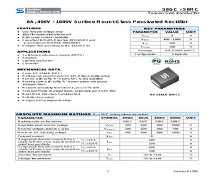
S8MC Taiwan Semiconductor 8A, 400V - 1000V Surface Mount Glass Passivated Rectifier FEATURES KEY PARAMETERS Low forward voltage drop Ideal for automated placement High surge current capability Compliant to RoHS Directive 2011/65/EU and in accordance to WEEE 2002/96/EC Halogen-free according to IEC 61249-2-21 PARAMETER VALUE UNIT IF(AV) 8 A VRRM 400 - 1000 V IFSM 200 A TJ MAX 150 C APPLICATIONS Switching mode power supply (SMPS) Adapters Lighting application Converter Package DO-214AB (SMC) Configuration Single die MECHANICAL DATA Case: DO-214AB (SMC) Molding compound meets UL 94V-0 flammability rating Part no. with suffix "H" means AEC-Q101 qualified Packing code with suffix "G" means green compound (halogen-free) Moisture sensitivity level: level 1, per J-STD-020 Terminal: Matte tin plated leads, solderable per J-STD-002 Meet JESD 201 class 2 whisker test DO-214AB (SMC) Polarity: As marked Weight: 0.27 g (approximately) ABSOLUTE MAXIMUM RATINGS (TA = 25C unless otherwise noted) SYMBOL PARAMETER
 5 Pages, 262 KB, Original
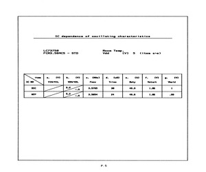
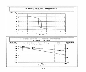
 . if 89 gt 99 7 a a 4 i i tL a q i i 1 j 4 3 -a:Vhold CVI 2 : 1 7 8 5 3 7 @ 4 4 4 a ft i I j I " -20 @ 20 40 68 8a Loading capacitance(CLi/(L2) dependence of oscillating characteristics (CLi=(L2) o-- Typical CLIVCL2 [pF]oun QS ON me oe Lc7375@ ~ DIC FCR3.S8MCS Ta= 28 [deg] @O Typical a. VIH/VIL [VI w----+% Worst rom, llc lg lg lv lg lg lg lg lg lg lg b. V2H/V2L [VI ry CL OO OO o-9 1 c. Fosc [xz] F * SSS SS emreeene 8-8 ~ ee ee d. Trise (CuSJ r : C e. Duty %] - o-0---- Senn 4 @ 1 2 3 4 5 6 7 Vdd [CVI] f. Vstart [VJ Typical = 1.86 Worst = 1.18 g. Vhold [CV] Typical = Worst = 1,13 Power supply voltage dependence of oscillating characteristicsauns Ww CO NE ew om LC73758 - MFP FCR3.S8MC5 Ta= 28 [deg] oS Typical a. VIH/VIL [VJ] %-----% Worst he - . i i i i 5 i L i at j l lj i 4 b. V2H/V2L CVI C a 2 C VeH a Vel 9 a A 2 a 1 c. Foss [%] Sg terrane 8-8 E } i 1 i i i L Ll i l i i Wl. 4 d. Trise [uSJ e. Duty [4%] F o--0 0-8 1 i lL } i l L L i L. l l i 4 | @ i 2 a 4 5 6 ? Vdd [VJ . Vstart [VI Ty
 12 Pages, 381 KB, Scan
Mc224 | 4.0 | 18MC22cA | 1.0 | 3smc22a | 1.0 1sMB24A | 1.0 | 9S5MB24CA | 1.0 | 18MC24a | 1.0 | 18MC24cA | 1.0 | agmc24a | 1.0 15MB26A | 1.0 | 15MB26CA | 1.0 | 18MC26A | 1.0 | 1SMCZecA | 1.0 | 3SMc26ea | 1.0 1SMB28A | 1.0 | 18MB28CA | 1.0 | 18MC28A | 1.0] 1S8MC28cA | 1.0 | 3smc2ea | 1.0 1SMB30A | 1.0 | 1SMB30CA | 1.0] 18Mc30A | 1.0] 1S8MC30CcA | 1.0 | 3SMc30A | 1.0 SELECT 1SMB33A | .0 | 18MB33CA | 1.0 | 18mca3A | 1.0] 1S8MC33CcA | 1.0 | 3SMC33A | 1.0 GUIDE 1smB36A_| 1.0 | 1SMB36CA | 4.0 | 18MC36A | 1.0 | 1S8MC36eca | 1.0 | 3smc36a_ | 1.0 1SMB40A_| 1.0 | 1SMB40CA | 1.0 | 1SMC40A | 1.0 | 1SMC40CA | 1.0 | 3SMC40A | 1.0 1smMB43A | 1.0 | 1smB4aca | 1.0 | 1SMC43A | 1.0] 18MC43cA | 1.0 | 3smca3A | 1.0 ismB4sA | 1.0 | 1smB4sca | 1.0 | 1smcasa | 1.0 | 1smc4asca | 1.0 | 3smcasa | 1.0 1SMB48A | 1.0 | 1S8MB48CA | 1.0 | 1SMC48a | 1.0 | 1SMC48CA | 1.0 | 3SMC48A | 1.0 isMB51A | 1.0 | 18MB51CA | 1.0 | 18mcsi1A | 1.0 | 18MC51CA | 1.0 | 3SMc51A | 1.0 18MB54A | 1.0 | 18MB54CA |
 30 Pages, 810 KB, Scan
art [VI *) { ~ a 1.62 1.63 1.65 1.66 1.67 1.69 1.72 4 1 i ' 4 re | L A i i i l 4 L i l lL il 3 - Vhold [V) 2 1.4 1.42 1.45 1.46 1.49 1.53 1.58 7 1 Q t lL iL i j i i i i 1 i 1 i 7 ~188 @ 108 208 308 488 500 600 M37421M6 - Rd Rf CMohm] 1 a. VIH/VIL CVI FCR3.S8MCS Vdd= 5 CV) (Fig.a~d) Ta= 28 Cdeg] o-- Typical Rd Cohm] Damping resistance(Rd) dependence of oscillating characteristicsoun Qo uN = om M37421M6 - 1 RF C[Mohm] 1 FCR3.S8MCS Rd Cohm) 158 Ta= 280 (deg) oO Typical a. VIH/VIL [VJ -----% Worst Ls 7 ViIH_ @- ~O -@ f : ' VIL eas >; = J \ 7 b. VeH/V2L CV] F V2H @ fn ~-@ : FU , , 4 c. Fose (%] : o 2 2. - d. Trise (CuS] wd : 2 $ i $ ri $ L 4 e. Duty [%1] r 3 = C = == === J 4 4.5 5 5.5 6 Vdd (CV) f. Vstart CV] Typical = 1.66 Worst = 1.73 g. Vhold CV] Typical = 1.46 Worst = 1.62 Power supply voltage dependence of oscillating characteristicsM37421M6 - 1 Rf (Mohm] 1 FCR3.S8MCS Rd Cohm] 15@ Vdd= 5 (V] (Fig.a~e) o Typical a. VIH/VIL CV) ? C e 4.7 4.7 4. sf vin 433-4:5 48 : ? : 3 E
 8 Pages, 233 KB, Scan
 16.7 1.0 24.4 61.5 5.0 | GEM iSMC16 16 17.8 1.0 28.8 52.1 5.0 GEN 1SMCI6A 16 17.8 1.0 26.0 57.7 5.0 GEP 1SMC17 17 18.9 1.0 30.5 49.2 5.0 GEQ 1SMC17A 17 18.9 1.0 27.6 53.3 5.0 GER 4SMC18 18 20.0 1.0 32.2 46.6 5.0 GES 1SMC18A 18 20.0 4.0 29,2 51.4 5.0 GET 1S8MC20 20 22.2 1.0 35.8 41.9 5.0 GEU 1SMC20A 20 22.2 1.0 32.4 46.3 : 5.0 GEV 1SMC22 22 24.4 1.0 39.4 38,1 5.0 GEW 1SMC22A 22 24.4 1.0 35.5 42,2 5.0 GEX 1SMC24 24 26.7 1.0 43.0 34.9 5.0 GEY ISMC24A 24 26.7 1.0 38.9 38.6 5.0 GEZ 1S8MC26 26 28.9 1.0 46.6 32.2 5.0 GFD iSMC26A 26 28,9 1.0 42.1 35.6 5.0 GFE 1SMC28 28 31.1 4.0 50,0 30.0 5.0 GFF ISMC28A 28 31.1 1.0 45.4 33.0 5.0 GFG 1S8MC30 30 33.3 1.0 53.5 28.0 5.0 GFH 1SMC30A 30 33.3 1.0 48.4 31.0 5.0 GFK 1SMC33 33 36.7 1.0 59,0 25.2 5.0 GFL 1SMC33A 33 36.7 1.0 53.3 28.1 5.0 GFM iSMC36 36 40.0 1.0 64.3 23.3 5.0 GFN 1SMC36A 36 40.0 4.0 58.1 25.8 5.0 GFP 1SMC40 40 44.4 4.0 71.4 21.0 5.0 GFa 1SMC40A : 40 44.4 1.0 64.5 32.2 5.0 GFR ISMC43 43 47.8 1.0 76.7 19.6 5.0 GFS 1SMC43A 43
 4 Pages, 214 KB, Scan
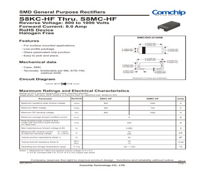
S8MC-HF Reverse Voltage: 800 to 1000 Volts Forward Current: 8.0 Amp RoHS Device Halogen Free SMC/DO-214AB Features 0.276(7.00) 0.256(6.50) - For surface mounted applications. - Low profile package. 0.128(3.25) 0.108(2.75) 0.244(6.20) 0.220(5.60) - Glass passivated chip junction. - Easy to pick and place. 0.315(8.00) 0.299(7.60) Mechanical data 0.012(0.31) 0.006(0.15) 0.094(2.39) 0.079(2.00) - Case: SMC - Terminals: Solderable per MIL-STD-750, method 2026. 0.063(1.60) 0.035(0.90) 0.008(0.21) 0.002(0.05) Dimensions in inches and (millimeter) Circuit Diagram Anode Cathode Maximum Ratings and Electrical Characteristics Ratings at 25C ambient temperature unless otherwise specified. Single phase, half wave, 60Hz resistive or inductive load, for capacitive load, derate by 20% Symbols S8KC-HF S8MC-HF Units Maximum repetitive peak reverse voltage VRRM 800 1000 V Maximum RMS voltage VRMS 560 700 V Maximum DC blocking voltage VDC 800 1000 V Maximum average forward rectified current IF(AV) 8 A P
 4 Pages, 455 KB, Original
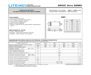
S8MC REVERSE VOLTAGE - 400 to 1000 Volts FORWARD CURRENT - 8.0 Amperes SURFACE MOUNT GLASS PASSIVATED RECTIFIERS SMC FEATURES Glass passivated chip For surface mounted applications Low reverse leakage current Low forward voltage drop High current capability Plastic material has UL flammability classification SMC A B DIM. MIN. MAX. A 6.60 7.11 B 5.59 6.22 C 2.92 3.18 D 0.15 0.31 E 7.75 8.13 F 0.05 0.20 G 2.01 2.50 H 0.76 1.52 C 94V-0 G MECHANICAL DATA H D F E Case : Molded plastic Polarity : Color band denotes cathode Weight : 0.007 ounces, 0.21 grams All Dimensions in millimeter MAXIMUM RATINGS AND ELECTRICAL CHARACTERISTICS Ratings at 25 ambient temperature unless otherwise specified. CHARACTERISTICS Maximum Recurrent Peak Reverse Voltage Maximum RMS Voltage Maximum DC Blocking Voltage Maximum Average Forward Rectified Current SYMBOL S8GC S8JC S8KC S8MC UNIT VRRM VRMS VDC 400 280 400 600 420 600 800 560 800 1000 700 1000 V V V I(AV) 8.0 A IFSM 200 A VF 0.985 V IR 10 250 uA Typical J
 3 Pages, 76 KB, Original
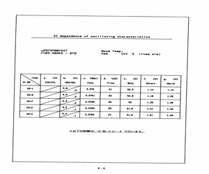
y Vstart Vhold CU-1 5.6 3 3.576 21 $3.2 1.14 1.14 cu-3 5.5 2 | 3.5761 23 $2.8 1.18 1.22 Cu-? 5.5 2 | 3.5762 22 53 1.33 1.32 Cu-2 5.5 1 | 3-876 25 $1.6 1.47 1.46 CU-4 5.4 1 | 395762 24 $1.6 1.51 1.49 * UR ORRIS, IC NO.CU4 CHEF,158 uPD?SP@@876GT - CU-4 FCR3.S8MCS Ta= 20 (deg) o Typical a. VIH/VIL [CV] #----4 Worst TITEere LELLLLI i... i L 1 4. ai 4 L b. VeH/VeL CVI - 1 L Val. 0-9- 1 - o- i o=- L 6 c. Fosc %] PPrErrire d. Ttrise tus) TrtriOgs LULLLLL e. Duty [%] ee ee ee f. Vstart [VJ Typical 1.48 Worst 1.51 g. Vhold ([V) Typical Worst a | o ome s..Ucl an m& No Power supply voltage dependence of oscillating characteristicsuPD?SP8@876GT - CU-4 FCR3.S58MCS Vdd= S (VJ (Fig.a~e) o@ Typical > aa: VIH/VIL CVI sf : 3 F ; q b. VeH/VeL_ CVI 3 fF 7 rf a 2 2 3 3 a =~} r A , Vel. a a A s s b 1 i a i z 1 t I 4 5S ct Fosc [%] 23F 7 al a . B17 | ~. 0856 8 .8856 8828 =~! a 3 -.3 : 3 -.5 i i i L i i 3 i i a i mY a 2 2 a i i 2a d. Trise (CuSJ 158 - ; 168 r 4 se 3S lg 36 31 1 ca e. Duty [%] 55 fF $1.5 2354.6 SS 53,5 5
 7 Pages, 157 KB, Scan
 wee 182.7 Wevak 20 & TEI aee entneec _ 390 i ~NMas Piva, Pe } 19 + ! - ee ae Q Q 10 28 F = -98 -30 + - -49 ! Lot peut l pip yp tii gg 1 18 188fo eg 1 Qee We = WwW ON em = & ON =~ MV wo mt S88 Su > wm Ui aoua > a 8 - my WwW @ MS@9539 - Rd Rf {Mohm] 1 FCR3.S8MCS Vdd= 5 (VJ (Fig.a~d) Ta= 20 (deg) -- Typical a. VIH/VIL [CV] POM TESS 52 4g 47 4,8 ' m2 -.2 7.7? -6 73 =f 4 b. V2H/VeL [V] T V2H 5.3 5.2 5.2 $\2 5.2 5.2 5.2 x F - e we vei ~e ws ~.1 4 r Vel 4 2 =2 lL Ai Z. 1 nd A i c. Fose [%) FE 9 a3; 062 td 13 215 : a , I E | y d. Trise ([CuS] r 4 | E a a 8s a6 7 e. Duty [%] r 4g 48.7 48.8 49,0 58,4 52.3 58 4 5 _ 5 f. Vstart [VJ] | r 1.45 1,46 1.49 15 1.52 1.55 1,58 ; - Vhold [CV] 1.31111 1.14 116 1.18 1.23 1.28 _ lL A L L i LL 1 L L. 1 i i 7 -168 8 18 200 308 400 580 622 Rd Cohm] Damping resistance(Rd) dependence of oscillating characteristicste wan oan M5@959 - 1 Rf {Mohm] 1 FCR3.S58MCS Rd Cohm] 158 Ta= 20 (deg) o--0 Typical a. VIH/VIL (CV) ----% Worst ' VIM Qezceeadpeneerenteerernn a ; eS a 1 b. V2H/V
 8 Pages, 240 KB, Scan
s: * RANGE=1 * BDIV=00 (divide by 1), RDIV 010 * BDIV=01 (divide by 2), RDIV 011 * BDIV=10 (divide by 4), RDIV 100 * BDIV=11 (divide by 8), RDIV 101 12.4.9 BDC Clock Operation When the bdm_enable signal is high, the <> will generate a clock (ICS8MCLK). This clock will be muxed with CORECLK (the core clock from the SIM module) and the output of this mux (ICSLCLK) will be provided for system communication with the Background Debug Controller (BDC). The mux will select CORECLK during reset or CLKSW is high, and it will select ICS8MCLK when CLKSW is low and not in reset. The frequency of ICS8MCLK is targeted at 512 times the filter frequency(rdiv_clk). 12.4.10 Scan Coverage The ICS hardblock will contain a ripple counter to be used for the reference divider. This counter will not be scannable. The operation of the ripple counter can be tested by observing the RDIV output clock signal. The ICS hardblock will also contain a ripple counter to be used for the bus fre
 372 Pages, 2189 KB, Original