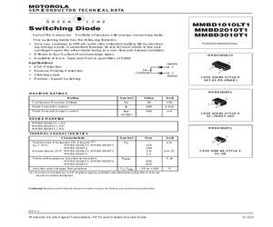
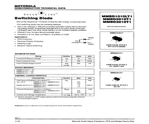
eas- ing energy waste. Guaranteed leakage limit is for each diode in the pair contingent upon the other diode being in a non-forwardbiased condition. * Offered in four Surface Mount package types Order this document by MMBD1010LT1/D MMBD1010LT1 MMBD2010T1 MMBD3010T1 Motorola Preferred Devices MMBD1010LT1 Available in 8 mm Tape and Reel in quantities of 3,000 Applications ANODE 3 e ESD Protection -_lqo 1 1 * Reverse Polarity Protection 30% . y CATHODE. 2 2 e Steering Logic ANODE . anki CASE 318-08, STYLE 9 MediumSpeed Switching SOT-23 (TO-236AB) MAXIMUM RATINGS MMBD201071 Rating Symbol Value Unit 3 Continuous Reverse Voltage VA 30 Vde 1 hs Peak Forward Current Ie 200 mAdc a Peak Forward Surge Current lem 500 mA (surge) CASE 419-02, STYLE 5 SC-70/SOT-323 DEVICE MARKING MMBD1010LT1 = A5 MMBD2010T1 = DP MMBD3010T1 = XS MMBD3010T1 THERMAL CHARACTERISTICS Characteristic Symbol Max Unit > Total Device Dissipation FR-4 Board (1) Pp mw 2 Ta = 25C MMBD1010LT1, MMBD3010T 1 225 1 MM
 8 Pages, 282 KB, Scan
 Case 318-08 -- TO-236AB (SOT-23) BAV170LT1 BAV199LT1 BAW156LT1 MMBD1005LT1 MMBD1010LT1 JX JY JZ A3 A5 70 70 70 30 30 100 100 100 100 100 Case 419-02 -- (SOT-323)/(SC-70) -- DUAL MMBD2005T1 MMBD2010T1 DI DP 30 30 Case 318D-04 -- (SC-59) -- DUAL MMBD3005T1 MMBD3010T1 XQ XS 30 30 (30) V = 0 V, f = 1.0 MHz R Devices listed in bold, italic are Motorola preferred devices. Selector Guide 1-34 Motorola Small-Signal Transistors, FETs and Diodes Device Data Multiple Switching Diodes Multiple diode configurations utilize monolithic structures fabricated by the planar process. They are designed to satisfy fast switching requirements as in core driver and encoding/decoding applications where their monolithic configurations offer lower cost, higher reliability and space savings. 14 16 1 1 CASE 751A-03 SO-14 PLASTIC CASE 751B-05 SO-16 PLASTIC Diode Array Diagrams 1 4 11 Dual 10 Diode Array 3 8 9 10 13 14 1 4 5 6 12 7 2 2 3 5 7 9 11 12 2 3 5 7 8 9 11 12 14 Dual 8 Diode Array 3 11 12 7 5 4 3 2 1 8 9 10 11 12 13
 1354 Pages, 24604 KB, Original
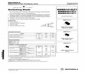
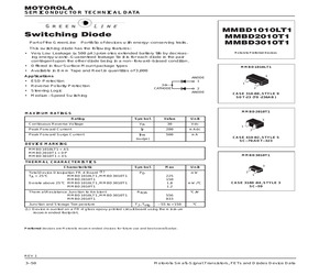
ste. Guaranteed leakage limit is for each diode in the pair contingent upon the other diode being in a nonforward-biased condition. Offered in four Surface Mount package types e Available in 8 mm Tape and Reel in quantities of 3,000 MMBD1010LT1 MMBD2010T1 MMBD3010T1 Motorola Preferred Devices MMBD1010LT1 2 CASE 318-07, STYLE 9 SOT-23 (TO-236AB) MMBD2010T1 ] 8 2! CASE 419-02, STYLE 5 SC-70/SOT-323 MMBD3010T1 1 CASE 318D-03, STYLE 3 SC-59 Applications e ESD Protection e Reverse Polarity Protection ANODE e Steering Logic 3044 i 1 e Medium-Speed Switching CATHODE id Oo 2 ANODE MAXIMUM RATINGS Rating Symbol Value Unit Continuous Reverse Voltage VR 30 Vdc Peak Forward Current IF 200 mAdc Peak Forward Surge Current lFM 500 mA (surge) DEVICE MARKING MMBD1010LT1 = A5 MMBD2010T1 = DP MMBD3010T1 = XS THERMAL CHARACTERISTICS Characteristic Symbol Max Unit Total Device Dissipation FR-4 Board (1) Pp mw Ta = 25C MMBD1010LT1, MMBD3010T 1 225 MMBD2010T1 150 Derate above 25'C MMBD1010LT1,
 8 Pages, 255 KB, Scan
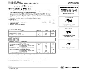
e. Guaranteed leakage limit is for each diode in the pair contingent upon the other diode being in a nonforward-biased condition. e Offered in four Surface Mount package types e Available in 8 mm Tape and Reel in quantities of 3,000 MMBD1010LT1 MMBD2010T1 MMBD3010T1 Motorola Preferred Devices Applications e ESD Protection ANODE 1 Reverse Polarity Protection 3 CATHODE 2 Steering Logic ANODE MediumSpeed Switching MMBD1010LT1 2 CASE 318-08, STYLE 9 SOT-23 (TO-236AB) MAXIMUM RATINGS MMBD2010T1 Rating Symbol Value Unit 3 Continuous Reverse Voltage VR 30 Vde 1 Peak Forward Current IF 200 mAdc 2 Peak Forward Surge Current lEM 500 mA (surge) CASE 419-02, STYLE 5 SC-70/SOT-323 DEVICE MARKING MMBOD1010LT1 = A5 MMBD2010T1 = DP MMBD3010T1 MMBD3010T1 = XS THERMAL CHARACTERISTICS x 1 CASE 318D-04, STYLE 3 Sc-59 Characteristic Symbol Max Unit Total Device Dissipation FR-4 Board (1) Pp mw Ta = 25C MMBD1010LT1, MMBD3010T1 225 MMBD2010T1 150 Derate above 25C MMBD1010LT1, 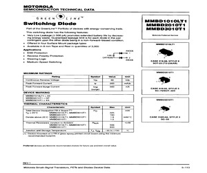 2 Pages, 51 KB, Scan
2 Pages, 51 KB, ScanMMBD3010T1 Switching Diode Part of the GreenLine Portfolio of devices with energy-conserving traits. This switching diode has the following features: * Very Low Leakage ( 500 pA) promotes extended battery life by decreasing energy waste. Guaranteed leakage limit is for each diode in the pair contingent upon the other diode being in a non-forward-biased condition. Motorola Preferred Devices * Offered in four Surface Mount package types MMBD1010LT1 * Available in 8 mm Tape and Reel in quantities of 3,000 Applications ANODE 1 * ESD Protection * Reverse Polarity Protection 3 CATHODE * Steering Logic * Medium-Speed Switching 2 ANODE Symbol Value 2 CASE 318-08, STYLE 9 SOT-23 (TO-236AB) Unit Continuous Reverse Voltage VR 30 Vdc Peak Forward Current IF 200 mAdc IFM (surge) 500 mA Peak Forward Surge Current 1 MMBD2010T1 MAXIMUM RATINGS Rating 3 3 1 2 CASE 419-02, STYLE 5 SC-70/SOT-323 DEVICE MARKING MMBD1010LT1 = A5 MMBD2010T1 = DP MMBD3010T1 = XS MMBD3010T1 THERMAL CHARACTERIST
 33 Pages, 292 KB, Original
MMBD3010T1 Switching Diode Part of the GreenLine Portfolio of devices with energy-conserving traits. This switching diode has the following features: * Very Low Leakage ( 500 pA) promotes extended battery life by decreasing energy waste. Guaranteed leakage limit is for each diode in the pair contingent upon the other diode being in a non-forward-biased condition. Motorola Preferred Devices * Offered in four Surface Mount package types MMBD1010LT1 * Available in 8 mm Tape and Reel in quantities of 3,000 Applications ANODE 1 * ESD Protection * Reverse Polarity Protection 3 CATHODE * Steering Logic * Medium-Speed Switching 2 ANODE Symbol Value 2 CASE 318-08, STYLE 9 SOT-23 (TO-236AB) Unit Continuous Reverse Voltage VR 30 Vdc Peak Forward Current IF 200 mAdc IFM (surge) 500 mA Peak Forward Surge Current 1 MMBD2010T1 MAXIMUM RATINGS Rating 3 3 1 2 CASE 419-02, STYLE 5 SC-70/SOT-323 DEVICE MARKING MMBD1010LT1 = A5 MMBD2010T1 = DP MMBD3010T1 = XS MMBD3010T1 THERMAL CHARACTERIST
 32 Pages, 289 KB, Original
d leakage limit is for each diode in the pair contingent upon the other diode being in a nonforwardbiased condition. e Offered in four Surface Mount package types e Available in 8 mm Tape and Reel in quantities of 3,000 Applications MMBD1010LT1 MMBD2010T1 MMBD3010T1 Motorole Preferred Devices MMBD1010LT1 ANODE e ESD Protection 1 1 e Reverse Polarity Protection 3 . . CATHODE 2 2 Steering Logic ANODE : ht CASE 318-08, STYLE 9 MediumSpeed Switching SOT-23 (TO-236AB) MAXIMUM RATINGS MMBD2010T1 Rating Symbol Value Unit 3 Continuous Reverse Voltage VA 30 Vde 1 Peak Forward Current Ie 200 mAdc 2 Peak Forward Surge Current {eM 500 mA (surge) CASE 419-02, STYLE 5 SC-70/SOT-323 DEVICE MARKING MMBD1010LT1 = AS MMBD2010T1 = DP MMBD3010T1 = XS MMBD3010T1 THERMAL CHARACTERISTICS Characteristic Symbol Max Unit by Totat Device Dissipation FR-4 Board (1) Pp mw 2 Ta = 25C MMBD1010LT1, MMBD3010T1 225 1 MMBD2010T1 150 Derate above 25C MMBD1010LT1, MMBD3010T1 1.8 mW
 2 Pages, 50 KB, Scan
-236AB) Unit Continuous Reverse Voltage VR 30 Vdc Peak Forward Current IF 200 mAdc IFM (surge) 500 mA Peak Forward Surge Current 1 MMBD2010T1 MAXIMUM RATINGS Rating 3 3 1 2 CASE 419-02, STYLE 5 SC-70/SOT-323 DEVICE MARKING MMBD1010LT1 = A5 MMBD2010T1 = DP MMBD3010T1 = XS MMBD3010T1 THERMAL CHARACTERISTICS Characteristic Symbol Total Device Dissipation FR-4 Board (1) TA = 25C MMBD1010LT1, MMBD3010T1 MMBD2010T1 Derate above 25C MMBD1010LT1, MMBD3010T1 MMBD2010T1 PD Thermal Resistance Junction to Ambient MMBD1010LT1, MMBD3010T1 MMBD2010T1 RJA Junction and Storage Temperature Max mW 225 150 1.8 1.2 TJ, Tstg 3 Unit 2 1 mW/C CASE 318D-04, STYLE 3 SC-59 C/W 556 833 - 55 to +150 C (1) Device mounted on a FR-4 glass epoxy printed circuit board using the minimum recommended footprint. Preferred devices are Motorola recommended choices for future use and best overall value. GreenLine is a trademark of Motorola, Inc. Thermal Clad is a registered trademark o
 8 Pages, 87 KB, Original
 Case 318-08 -- TO-236AB (SOT-23) BAV170LT1 BAV199LT1 BAW156LT1 MMBD1005LT1 MMBD1010LT1 JX JY JZ A3 A5 70 70 70 30 30 100 100 100 100 100 Case 419-02 -- (SOT-323)/(SC-70) -- DUAL MMBD2005T1 MMBD2010T1 DI DP 30 30 Case 318D-04 -- (SC-59) -- DUAL MMBD3005T1 MMBD3010T1 XQ XS 30 30 (30) V = 0 V, f = 1.0 MHz R Devices listed in bold, italic are Motorola preferred devices. Small Signal Transistors, FETs and Diodes 5.1-38 Motorola Master Selection Guide Multiple Switching Diodes Multiple diode configurations utilize monolithic structures fabricated by the planar process. They are designed to satisfy fast switching requirements as in core driver and encoding/decoding applications where their monolithic configurations offer lower cost, higher reliability and space savings. 14 14 16 16 1 1 1 1 CASE 646-06 PIN DIP PLASTIC CASE 648-08 PIN DIP PLASTIC CASE 751A-03 SO-14 PLASTIC CASE 751B-05 SO-16 PLASTIC Diode Array Diagrams Dual 10 Diode Array 7 1 3 4 12 13 14 5 8 9 10 11 2 6 8 Diode Array (Common Cathode) 1
 43 Pages, 309 KB, Original
 Case 318-08 -- TO-236AB (SOT-23) BAV170LT1 BAV199LT1 BAW156LT1 MMBD1005LT1 MMBD1010LT1 JX JY JZ A3 A5 70 70 70 30 30 100 100 100 100 100 Case 419-02 -- (SOT-323)/(SC-70) -- DUAL MMBD2005T1 MMBD2010T1 DI DP 30 30 Case 318D-03 -- (SC-59) -- DUAL MMBD3005T1 MMBD3010T1 XQ XS 30 30 (30) V = 0 V, f = 1.0 MHz R Devices listed in bold, italic are Motorola preferred devices. Motorola Master Selection Guide 5.1-37 Small Signal Transistors, FETs and Diodes Multiple Switching Diodes Multiple diode configurations utilize monolithic structures fabricated by the planar process. They are designed to satisfy fast switching requirements as in core driver and encoding/decoding applications where their monolithic configurations offer lower cost, higher reliability and space savings. 14 14 16 16 1 1 1 1 CASE 646-06 PIN DIP PLASTIC CASE 648-08 PIN DIP PLASTIC CASE 751A-03 SO-14 PLASTIC CASE 751B-05 SO-16 PLASTIC Diode Array Diagrams Dual 10 Diode Array 7 1 3 4 12 13 14 5 8 9 10 11 2 6 8 Diode Array (Common Cathode) 1
 42 Pages, 292 KB, Original
 Case 318-08 -- TO-236AB (SOT-23) BAV170LT1 BAV199LT1 BAW156LT1 MMBD1005LT1 MMBD1010LT1 JX JY JZ A3 A5 70 70 70 30 30 100 100 100 100 100 Case 419-02 -- (SOT-323)/(SC-70) -- DUAL MMBD2005T1 MMBD2010T1 DI DP 30 30 Case 318D-03 -- (SC-59) -- DUAL MMBD3005T1 MMBD3010T1 XQ XS 30 30 (30) V = 0 V, f = 1.0 MHz R Devices listed in bold, italic are Motorola preferred devices. Motorola Master Selection Guide 5.1-37 Small Signal Transistors, FETs and Diodes Multiple Switching Diodes Multiple diode configurations utilize monolithic structures fabricated by the planar process. They are designed to satisfy fast switching requirements as in core driver and encoding/decoding applications where their monolithic configurations offer lower cost, higher reliability and space savings. 14 14 16 16 1 1 1 1 CASE 646-06 PIN DIP PLASTIC CASE 648-08 PIN DIP PLASTIC CASE 751A-03 SO-14 PLASTIC CASE 751B-05 SO-16 PLASTIC Diode Array Diagrams 4 1 1 Dual 10 Diode Array 7 1 3 4 12 13 14 5 8 9 10 11 2 6 8 Diode Array (Common Cath
 41 Pages, 293 KB, Original
.1-36 MMBD2836LT1 . . . . . . . . . . . . . . 5.1-36 MMBD2837LT1 . . . . . . . . . . . . . . 5.1-36 MMBD2838LT1 . . . . . . . . . . . . . . 5.1-36 MMBD3000T1 . . . . . . . . 5.1-36, 5.1-41 MMBD3005T1 . . . . . . . . 5.1-37, 5.1-41 7.1-17 Device Index Page MMBD3010T1 . . . . . . . . 5.1-37, 5.1-41 MMBD6050LT1 . . . . . . . . . . . . . . 5.1-35 MMBD6100LT1 . . . . . . . . . . . . . . 5.1-36 MMBD7000LT1 . . . . . . . . . . . . . . 5.1-36 MMBF170LT1 . . . . . . . . . . . . . . . . 5.1-23 MMBF0201NLT1 . . . . . . 5.1-23, 5.1-41 MMBF0202PLT1 . . . . . . 5.1-23, 5.1-41 MMBF2201NT1 . . . . . . . . . . . . . . 5.1-41 MMBF2201PT1 . . . . . . . . . . . . . . 5.1-23 MMBF2202NT1 . . . . . . . . . . . . . . 5.1-23 MMBF2202PT1 . . . . . . . . . . . . . . 5.1-41 MMBF4391LT1 . . . . . . . . . . . . . . . 5.1-23 MMBF4392LT1 . . . . . . . . . . . . . . . 5.1-23 MMBF4393LT1 . . . . . . . . . . . . . . . 5.1-23 MMBF4416LT1 . . . . . . . . . . . . . . . 5.1-22 MMBF4856LT1 . . . . . . . . . . . . . . . 5.1-23 MMBF4860L
 48 Pages, 137 KB, Original
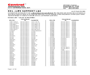
00T1 ON Semi (MOT) Zetex Consult Factory MMBD2005T1 ON Semi (MOT) * FXTA42 * FXTA92 Zetex Consult Factory MMBD2010T1 ON Semi (MOT) Zetex Consult Factory MMBD2838LT1 ON Semi (MOT) * FZT2222A * FZT2907A Zetex CZT2222A MMBD3005T1 ON Semi (MOT) Zetex CZT2907A MMBD3010T1 ON Semi (MOT) * FZT4403 * FZTA63 Zetex CZT2907A MMBR2857LT1 ON Semi (MOT) In Development Zetex CZTA64 MMBR5179 ON Semi (MOT) CMPT5179 MBD101 ON Semi (MOT) 1N6263 TR ON Semi (MOT) CMPT404A TR MBR120P ON Semi (MOT) CRSH1-4 Microsemi CMPT2222A MBR360 ON Semi (MOT) CRSH3-6 Microsemi CMPT2907A Page 15 of 18 MMBT404ALT1 * MMBT2222A * MMBT2907A CMPD2838 TR 145 Adams Avenue Hauppauge, NY 11788 Phone (631) 435-1110 Fax (631) 435-1824 www.centralsemi.com/eol EOL -LIFE SUPPORT List as of: March 30, 2001 Central Semiconductor Corp. will continue to manufacture the discrete semiconductors included on this list as long as there is an industry demand. For an update of this list please contact your sales representative or visit our website at www.cen
 18 Pages, 80 KB, Original
-< ,, `?.!r.: ,> 820 Q tiov 2k 0.1 UF ,R_mA 50 Q INPUT SAMPLING OSCILLOSCOPE I OUTPUTPULSE (IF = IR = 10 m% measured at iR(REC)= i mA) I 10 mA. -- -- -- - 2 Motorola Small-Signal Transistors, FETs and Diodes Device Data MMBD101 OLT1 MM BD201 OTI MMBD3010T1 MINIMUM RECOMMENDED -- -- FOOTPRINT Sutiace mount board layout is a critical potiion of the total design. The footprint for the semiconductor packages must be the correct size to insure proper solder connection FOR SURFACE MOUNTED APPLICATIONS interface between the board and the package. With the correct pad geometry, the packages will self align when subjected to a solder reflow process. 0.037 G l_l 0094 1, SC-59 t n1.22 0.048 -- I -- -- 2,36 _ 0.093 4,19 0.165 u_ > mm inches SOD-1 23 A SURFACE The power dis~~;fi$o~ for a surface mount device is a function of the -,wcd~ector pad size. These can vary from the minimumt:~~~~~;~e for soldering to a pad size given for maximum Wshdlssipation. Power dissipation for a sutiace mount ~~~i~&is
 8 Pages, 658 KB, Original
 products * Extends battery life * Less power wasted through dissipation loss * Competitive edge in the war for energy savings GreenLine Energy-Conserving Devices * Switching Diode, Single, Leakage 500 pA MMBD3005T1 * Switching Diode, Dual, Leakage 500 pA MMBD3010T1 * Switching Diode, Dual, Leakage 500 pA MSD1010T1 * Bipolar PNP Transistor, VCE(sat) 100 MV MMBD1000LT1 * Switching Diode, Single, Leakage 500 pA MMBD1005LT1 * Switching Diode, Dual, Leakage 500 pA MMBD1010LT1 * Switching Diode, Dual, Leakage 500 pA MMBT1010LT1 * Bipolar PNP Transistor, VCE(sat) 100 MV MMBF0201NLT1 * Signal HDTMOS, N-Channel, rDS(on) 1 MMBF0202PLT1 * Signal HDTMOS, P-Channel, rDS(on) 1.4 MMBD2000T1 * Switching Diode, Single, Leakage 500 pA MMBD2005T1 * Switching Diode, Dual, Leakage 500 pA MMBD2010T1 * Switching Diode, Dual, Leakage 500 pA MMSD1000T1 * Switching Diode, Single, Leakage 500 pA MMBD3000T1 CPSTG KEY FOCUS PRODUCTS (continued) SMALL SIGNAL (continued) Device Key Features Types of Applications Product Benef
 24 Pages, 119 KB, Original