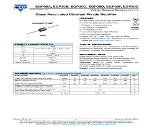
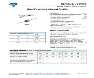
EGP30F, EGP30G www.vishay.com Vishay General Semiconductor Glass Passivated Ultrafast Plastic Rectifier FEATURES * Superectifier structure for high reliability condition SUPERECTIFIER * Cavity-free glass-passivated junction (R) * Ultrafast reverse recovery time * Low forward voltage drop * Low leakage current * Low switching losses, high efficiency * High forward surge capability GP20 * Solder dip 275 C max. 10 s, per JESD 22-B106 * Material categorization: for definitions of compliance please see www.vishay.com/doc?99912 PRIMARY CHARACTERISTICS TYPICAL APPLICATIONS IF(AV) 3.0 A VRRM 50 V, 100 V, 150 V, 200 V, 300 V, 400 V IFSM 125 A trr 50 ns VF 0.95 V, 1.25 V TJ max. 150 C Package GP20 Diode variations Single die For use in high frequency rectification and freewheeling application in switching mode converters and inverters for consumer, computer and telecommunication. MECHANICAL DATA Case: GP20, molded epoxy over glass body Molding compound meets UL 94 V-0 flammability rating Base P/N-E3 - RoHS
 5 Pages, 86 KB, Original
EGP30F, EGP30G www.vishay.com Vishay General Semiconductor Glass Passivated Ultrafast Plastic Rectifier FEATURES * Superectifier structure for high reliability condition SUPERECTIFIER * Cavity-free glass-passivated junction (R) * Ultrafast reverse recovery time * Low forward voltage drop * Low leakage current * Low switching losses, high efficiency * High forward surge capability GP20 * Solder dip 275 C max. 10 s, per JESD 22-B106 * AEC-Q101 qualified * Material categorization: For definitions of compliance please see www.vishay.com/doc?99912 TYPICAL APPLICATIONS For use in high frequency rectification and freewheeling application in switching mode converters and inverters for consumer, computer and telecommunication. PRIMARY CHARACTERISTICS IF(AV) 3.0 A VRRM 50 V, 100 V, 150 V, 200 V, 300 V, 400 V IFSM 125 A MECHANICAL DATA trr 50 ns VF 0.95 V, 1.25 V TJ max. 150 C Case: GP20, molded epoxy over glass body Molding compound meets UL 94 V-0 flammability rating Base P/N-E3 - RoHS-compliant, commerci
 4 Pages, 72 KB, Original
mmability Classification Rating 94V-0 and MSL rating 1 Maximum Ratings * * * DO-201AD Operating Temperature: -55OC to +150 OC Storage Temperature: -55OC to +150 OC Typical Thermal Resistance: 20OC/W Junction to Ambient MCC Part Number EGP30A EGP30B EGP30D EGP30F EGP30G EGP30J EGP30K Maximum Recurrent Peak Reverse Voltage 50V 100V 200V 300V 400V 600V 800V Maximum RMS Voltage Maximum DC Blocking Voltage 35V 70V 140V 210V 280V 420V 560V 50V 100V 200V 300V 400V 600V 800V D A Cathode Mark B Electrical Characteristics @ 25OC Unless Otherwise Specified Maximum Average Forward Current Peak Forward Surge Current Maximum Instantaneous Forward Voltage EGP30A-30D EGP30F-30G EGP30J-30K Maximum DC Reverse Current At Rated DC Blocking Voltage Reverse Recovery Time EGP30A-30G EGP30J-30K Typical Junction Capacitance EGP30A-30D EGP30F-30K IF(AV) 3.0 A TA = 55OC IFSM 125A 8.3ms, half sine VF 1.00V 1.25V 1.70V IF=3.0A TA=25OC IR 5.0uA 100uA TA=25OC TA=125 OC Trr CJ 50nS 75nS 95pF 75pF TA=25
 4 Pages, 108 KB, Original
rward voltage, high current capability Low leakage current Maximum Ratings * * * DO-201AE Operating Temperature: -55OC to +150 OC Storage Temperature: -55OC to +150 OC Typical Thermal Resistance: 20OC/W Junction to Ambient Part Number EGP30A EGP30B EGP30D EGP30F EGP30G EGP30J EGP30K Maximum Recurrent Peak Reverse Voltage 50V 100V 200V 300V 400V 600V 800V Maximum RMS Voltage Maximum DC Blocking Voltage 35V 70V 140V 210V 280V 420V 560V 50V 100V 200V 300V 400V 600V 800V D A Cathode Mark B Electrical Characteristics @ 25OC Unless Otherwise Specified Maximum Average Forward Current Peak Forward Surge Current Maximum Instantaneous Forward Voltage EGP30A-30D EGP30F-30G EGP30J-30K Maximum DC Reverse Current At Rated DC Blocking Voltage Reverse Recovery Time EGP30A-30G EGP30J-30K Typical Junction Capacitance EGP30A-30D EGP30F-30K IF(AV) 3.0 A TA = 55OC IFSM 125A 8.3ms, half sine VF 0.95V 1.25V 1.70V IF=3.0A TA=25OC 5.0uA 100uA TA=25OC TA=125 OC IR Trr CJ 50nS 75nS 95pF 75pF D C D
 3 Pages, 51 KB, Original
 TOSHIBA GOODARK GOODARK GOODARK GOODARK FT1213MH FT0813NH FT1213NH FS1210BH FS1210BH FS1210DH FS1210NH FS1610BH FS1610BH FS1610BH FS1610DH FS1610MH FS1614NH FS0102DA FUF2007 BYM26E FES3D FES3G FES3J FES3J FSS32 FSS34 MR852GP MR854GP MR856GP EGP30B EGP30D EGP30F EGP30G SB330 SB350 SB360 FB3500 FB3510 FB3501 FB3502 FB3504 FB3506 FB3508 FB3500 FB3510 FB3501 FB3502 FB3504 FB3506 FB3508 MR851GP 1N5624GP EGP30D ZY100 ZY100 ZY10 ZY10 3EZ110D10 3EZ110D5 3EZ11D10 3EZ11D5 3EZ120D10 3EZ120D5 3EZ12D10 3EZ12D5 3EZ130D10 3EZ130D5 3EZ13D10 3EZ13D5 3EZ150D10 3EZ150D5 3EZ15D10 3EZ15D5 3EZ160D10 3EZ160D5 3EZ16D10 3EZ16D5 3EZ180D10 3EZ180D5 3EZ18D10 3EZ18D5 3EZ200D10 3EZ200D5 3EZ20D10 3EZ20D5 3EZ22D10 3EZ22D5 3EZ24D10 3EZ24D5 3EZ27D10 3EZ27D5 3EZ30D10 3EZ30D5 3EZ33D10 3EZ33D5 3EZ36D10 3EZ36D5 3EZ39D10 3EZ39D5 3EZ43D10 3EZ43D5 3EZ47D10 3EZ47D5 3EZ51D10 3EZ51D5 3EZ56D10 3EZ56D5 3EZ62D10 3EZ62D5 3EZ68D10 GOODARK GOODARK GOODARK GOODARK GOODARK GOODARK GOODARK GOODARK GOODARK GOODARK GOODARK GOODARK GOODARK GOODARK GO
 136 Pages, 7525 KB, Original
IA. *Glass Encapsulation technique is covered by Patent No. 3,996,602, brazed-lead assembly to Patent No. 3,930,306 Maximum Ratings & Thermal Characteristics Ratings at 25C ambient temperature unless otherwise specified. Symbol EGP30A EGP30B EGP30C EGP30D EGP30F EGP30G Parameter Unit Maximum repetitive peak reverse voltage VRRM 50 100 150 200 300 400 V Maximum RMS voltage VRMS 35 70 105 140 210 280 V Maximum DC blocking voltage VDC 50 100 150 200 300 400 V Maximum average forward rectified current 0.375" (9.5mm) lead length at TA = 55C IF(AV) 3.0 A Peak forward surge current 8.3ms single half sine-wave superimposed on rated load IFSM 125 A RJA RJL 20 8.0 C/W TJ,TSTG -65 to +150 C Typical thermal resistance (Note 1) Operating and storage temperature range Electrical Characteristics Ratings at 25C ambient temperature unless otherwise specified. Symbol EGP30A EGP30B EGP30C EGP30D EGP30F EGP30G Parameter Maximum instantaneous forward voltage at 2.0A 0.95 1.25 V IR 5.0 100 A Maximum rever
 2 Pages, 33 KB, Original
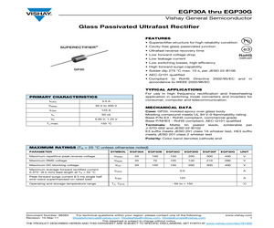
ix for high reliability grade (AEC Q101 qualified) Polarity: Color band denotes cathode end MAXIMUM RATINGS (TA = 25 C unless otherwise noted) PARAMETER SYMBOL EGP30A EGP30B EGP30C Maximum repetitive peak reverse voltage VRRM 50 Maximum RMS voltage EGP30D EGP30F EGP30G UNIT 100 150 200 300 400 V VRMS 35 70 105 140 210 280 V Maximum DC blocking voltage VDC 50 100 150 200 300 400 V Maximum average forward rectified current 0.375" (9.5 mm) lead length at TA = 55 C IF(AV) 3.0 A Peak forward surge current 8.3 ms single half sine-wave superimposed on rated load IFSM 125 A TJ, TSTG - 65 to + 150 C Operating and storage temperature range Document Number: 88584 Revision: 02-Jul-07 www.vishay.com 1 EGP30A thru EGP30G Vishay General Semiconductor ELECTRICAL CHARACTERISTICS (TA = 25 C unless otherwise noted) PARAMETER TEST CONDITIONS SYMBOL EGP30A EGP30B EGP30C EGP30D EGP30F EGP30G UNIT Maximum instantaneous forward voltage at 3.0 A VF Maximum DC reverse current at rated DC blocking voltage TA =
 4 Pages, 89 KB, Original
 * * EGP30A THRU EGP30K omponents 21201 Itasca Street Chatsworth !"# $ % !"# DO-201AE Operating Temperature: -55OC to +150 OC Storage Temperature: -55OC to +150 OC Typical Thermal Resistance: 20OC/W Junction to Ambient MCC Part Number EGP30A EGP30B EGP30D EGP30F EGP30G EGP30J EGP30K Maximum Recurrent Peak Reverse Voltage 50V 100V 200V 300V 400V 600V 800V Maximum RMS Voltage Maximum DC Blocking Voltage 35V 70V 140V 210V 280V 420V 560V 50V 100V 200V 300V 400V 600V 800V D A Cathode Mark B Electrical Characteristics @ 25OC Unless Otherwise Specified Maximum Average Forward Current Peak Forward Surge Current Maximum Instantaneous Forward Voltage EGP30A-30D EGP30F-30G EGP30J-30K Maximum DC Reverse Current At Rated DC Blocking Voltage Reverse Recovery Time EGP30A-30G EGP30J-30K Typical Junction Capacitance EGP30A-30D EGP30F-30K IF(AV) 3.0 A TA = 55OC IFSM 125A 8.3ms, half sine VF 0.95V 1.25V 1.70V IF=3.0A TA=25OC 5.0uA 100uA TA=25OC TA=125 OC IR Trr CJ 50nS 75nS 95pF 75pF D C D
 3 Pages, 81 KB, Original
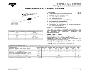
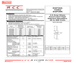
TD-002 and JESD 22-B102 E3 suffix meets JESD 201 class 1A whisker test, HE3 suffix meets JESD 201 class 2 whisker test Polarity: Color band denotes cathode end MAXIMUM RATINGS (TA = 25 C unless otherwise noted) PARAMETER SYMBOL EGP30A EGP30B EGP30C EGP30D EGP30F EGP30G UNIT Maximum repetitive peak reverse voltage VRRM 50 100 150 200 300 400 V Maximum RMS voltage VRMS 35 70 105 140 210 280 V Maximum DC blocking voltage VDC 50 100 150 200 300 400 V Maximum average forward rectified current 0.375" (9.5 mm) lead length at TA = 55 C IF(AV) 3.0 A Peak forward surge current 8.3 ms single half sine-wave superimposed on rated load IFSM 125 A TJ, TSTG - 65 to + 150 C Operating and storage temperature range Document Number: 88584 Revision: 01-Feb-11 For technical questions within your region, please contact one of the following: DiodesAmericas@vishay.com, DiodesAsia@vishay.com, DiodesEurope@vishay.com www.vishay.com 1 EGP30A thru EGP30G Vishay General Semiconductor ELECTRICAL CHARACTERISTICS (TA = 25 C unle
 4 Pages, 78 KB, Original
mmability Classification Rating 94V-0 and MSL rating 1 Maximum Ratings * * * DO-201AD Operating Temperature: -55OC to +150 OC Storage Temperature: -55OC to +150 OC Typical Thermal Resistance: 20OC/W Junction to Ambient MCC Part Number EGP30A EGP30B EGP30D EGP30F EGP30G EGP30J EGP30K Maximum Recurrent Peak Reverse Voltage 50V 100V 200V 300V 400V 600V 800V Maximum RMS Voltage Maximum DC Blocking Voltage 35V 70V 140V 210V 280V 420V 560V 50V 100V 200V 300V 400V 600V 800V D A Cathode Mark B Electrical Characteristics @ 25OC Unless Otherwise Specified Maximum Average Forward Current Peak Forward Surge Current Maximum Instantaneous Forward Voltage EGP30A-30D EGP30F-30G EGP30J-30K Maximum DC Reverse Current At Rated DC Blocking Voltage Reverse Recovery Time EGP30A-30G EGP30J-30K Typical Junction Capacitance EGP30A-30D EGP30F-30K IF(AV) 3.0 A TA = 55OC IFSM 125A 8.3ms, half sine VF 1.00V 1.25V 1.70V IF=3.0A TA=25OC IR 5.0uA 100uA TA=25OC TA=125 OC Trr CJ 50nS 75nS 95pF 75pF TA=25
 4 Pages, 109 KB, Original
 For use in high frequency rectification and freewheeling application in switching mode converters and inverters for consumer, computer and Telecommunication Maximum Ratings TA = 25 C unless otherwise specified Parameter Symbol EGP30A EGP30B EGP30C EGP30D EGP30F EGP30G Unit Maximum repetitive peak reverse voltage VRRM 50 100 150 200 300 400 V Maximum RMS voltage VRMS 35 70 105 140 210 280 V Maximum DC blocking voltage VDC 50 100 150 200 300 400 Maximum average forward rectified current 0.375" (9.5 mm) lead length at TA = 55 C IF(AV) 3.0 A Peak forward surge current 8.3 ms single half sine-wave superimposed on rated load IFSM 125 A TJ,TSTG - 65 to + 150 C Operating and storage temperature range Document Number 88584 10-Aug-05 V www.vishay.com 1 EGP30A thru EGP30G Vishay Semiconductors Electrical Characteristics TA = 25 C unless otherwise specified Parameter Test condition Maximum instantaneous forward voltage Symbol EGP30A EGP30B EGP30C EGP30D EGP30F EGP30G at 3.0 A 0.95 VF 1.25 Unit
 3 Pages, 213 KB, Original
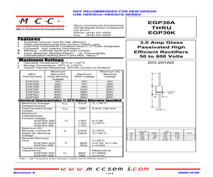
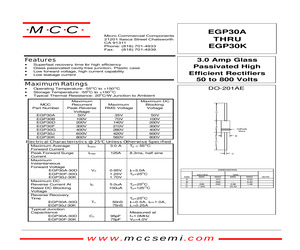
 EGP10A HER101G EGP10B HER102G EGP10D HER103G EGP10F HER104G EGP10G HER105G EGP10J HER106G EGP10K HER107G EGP20A HER201G EGP20B HER202G EGP20D HER203G EGP20F HER204G EGP20G HER205G EGP20J HER206G EGP20K HER207G EGP30A HER301G EGP30B HER302G EGP30D HER303G EGP30F HER304G EGP30G HER305G EGP30J HER306G EGP30K HER307G www.mccsemi.com MCC TM Micro Commercial Components EGP30A THRU EGP30K omponents 20736 Marilla Street Chatsworth !"# $ % !"# Features * * * x x 3.0 Amp Glass Passivated High Efficient Rectifiers 50 to 800 Volts Superfast recovery time for high efficiency Glass passivated cavity-free junction, Plastic case Lead Free Finish/RoHS Compliant (Note1) ("P"Suffix designates Compliant. See ordering information) Marking : Cathode band and type number Case Material: Molded Plastic. UL Flammability Classification Rating 94V-0 and MSL rating 1 Maximum Ratings * * * DO-201AD Operating Temperature: -55OC to +150 OC Storage Temperature: -55OC to +150 OC Typical Thermal Resistance: 20OC/W Junction to Amb
 5 Pages, 136 KB, Original
TD-002 and JESD 22-B102 E3 suffix meets JESD 201 class 1A whisker test, HE3 suffix meets JESD 201 class 2 whisker test Polarity: Color band denotes cathode end MAXIMUM RATINGS (TA = 25 C unless otherwise noted) PARAMETER SYMBOL EGP30A EGP30B EGP30C EGP30D EGP30F EGP30G UNIT Maximum repetitive peak reverse voltage VRRM 50 100 150 200 300 400 V Maximum RMS voltage VRMS 35 70 105 140 210 280 V Maximum DC blocking voltage VDC 50 100 150 200 300 400 V Maximum average forward rectified current 0.375" (9.5 mm) lead length at TA = 55 C IF(AV) 3.0 A Peak forward surge current 8.3 ms single half sine-wave superimposed on rated load IFSM 125 A TJ, TSTG - 65 to + 150 C Operating and storage temperature range Document Number: 88584 Revision: 15-Mar-11 For technical questions within your region, please contact one of the following: www.vishay.com DiodesAmericas@vishay.com, DiodesAsia@vishay.com, DiodesEurope@vishay.com 1 This datasheet is subject to change without notice. THE PRODUCT DESCRIBED HEREIN AND THIS
 4 Pages, 76 KB, Original
class 1A whisker test, HE3 suffix for high reliability grade (AEC Q101 qualified), meets JESD 201 class 2 whisker test Polarity: Color band denotes cathode end MAXIMUM RATINGS (TA = 25 C unless otherwise noted) PARAMETER SYMBOL EGP30A EGP30B EGP30C EGP30D EGP30F EGP30G UNIT Maximum repetitive peak reverse voltage VRRM 50 100 150 200 300 400 V Maximum RMS voltage VRMS 35 70 105 140 210 280 V Maximum DC blocking voltage VDC 50 100 150 200 300 400 V Maximum average forward rectified current 0.375" (9.5 mm) lead length at TA = 55 C IF(AV) 3.0 A Peak forward surge current 8.3 ms single half sine-wave superimposed on rated load IFSM 125 A TJ, TSTG - 65 to + 150 C Operating and storage temperature range Document Number: 88584 Revision: 20-Aug-07 For technical questions within your region, please contact one of the following: PDD-Americas@vishay.com, PDD-Asia@vishay.com, PDD-Europe@vishay.com www.vishay.com 1 EGP30A thru EGP30G Vishay General Semiconductor ELECTRICAL CHARACTERISTICS (TA = 25 C unless oth
 4 Pages, 105 KB, Original
TD-002 and JESD 22-B102 E3 suffix meets JESD 201 class 1A whisker test, HE3 suffix meets JESD 201 class 2 whisker test Polarity: Color band denotes cathode end MAXIMUM RATINGS (TA = 25 C unless otherwise noted) PARAMETER SYMBOL EGP30A EGP30B EGP30C EGP30D EGP30F EGP30G UNIT Maximum repetitive peak reverse voltage VRRM 50 100 150 200 300 400 V Maximum RMS voltage VRMS 35 70 105 140 210 280 V Maximum DC blocking voltage VDC 50 100 150 200 300 400 V Maximum average forward rectified current 0.375" (9.5 mm) lead length at TA = 55 C IF(AV) 3.0 A Peak forward surge current 8.3 ms single half sine-wave superimposed on rated load IFSM 125 A TJ, TSTG - 65 to + 150 C Operating and storage temperature range Document Number: 88584 Revision: 15-Mar-11 For technical questions within your region, please contact one of the following: www.vishay.com DiodesAmericas@vishay.com, DiodesAsia@vishay.com, DiodesEurope@vishay.com 1 This datasheet is subject to change without notice. THE PRODUCT DESCRIBED HEREIN AND THIS
 4 Pages, 78 KB, Original