/6 www.sensortechnics.com AWM42000 Series Mass flow sensor for gases FLOW SENSOR CHARACTERISTICS3 VS = 10 0.01 V, TA = 25C Part no. Flow range (full scale) Max. flow ch an g e4 Output voltage @ trim point AWM42150VH 2 5 sccm 5.0 l/sec 8.5 1.5 mV @ 25 sccm AWM42300V 1 0 0 0 sccm 5.0 l/sec 54.7 3.7 mV @ 1000 sccm PERFORMANCE CHARACTERISTICS VS = 10 0.01 V, TA = 25C Characteristics Zero offset Min. Typ. Max. AWM42150VH -1.0 0 1.0 AWM42300V -1.5 0 1.5 Repeatability and hysteresis AWM42150VH 0.35 (combined) AWM42300V 0.50 Temperature effects5 Offset -25 to 85 C 0.20 Span -25 to 25 C 2.5 25 to 85 C -2.5 Response time Common mode pressure 1.0 Unit mV % reading mV % reading 3.0 ms 150 p si Notes: 3 A 5 micron filter is recommended for all devices. 4 Maximum allowable rate of flow change to prevent damage. 5 Shift is relative to 25 C. 2/6 November 2004 / 624 www.sensortechnics.com AWM42000 Series Mass flow sensor for gases OUTPUT FLOW VS INTERCHANGEABILITY VS = 10 0.01 V, TA = 25
 6 Pages, 195 KB, Original
 or temperature changes will affect sensor output. +vs (10 VDC) Vs (10 VDC) 5K PIN 4 1.82 K _ LM2902 PIN 3 + PIN 5 PIN 1 Figure 2, Sensing Bridge Supply Circuit *24.9K *500 *Use trimpot to balance Vs - Pin 2 and Vs - Pin 6 AWM42150VH 25 sccm/ 0.008 in H2O AWM42300V 1000 sccm/ 1.0 in H2O AWM43300V + 1000 sccm/+ 1.0 in H2O AWM43600V + 6 SLPM/+ 8.0 in H2O LM2902 Sensing and Control + _1/4 R4 R3 R2 _ R1 1/4 + LM2902 R2 PIN 6 (V2 ) Media flow through the sensor should be free of condensing moisture and particulates. Large, highvelocity particles or conductive particles may damage the sensing element. Use of an inexpensive 5 micron filter, upstream of the sensing element, is recommended. *24.9K Figure 3, Differential Instrumentation Amplifier (Optional) DESCRIPTION Flow Range PIN 6 S resistance PIN 2 (V1 ) Catalog Listing PIN 2 R3 _ 1/4 + R4 V 0 +Vs R5 V OFFSET LM2902 R6 Equation 1 2R2 + R1 R4 VO = V - V + Voffset R1 R3 2 1 ( ) where R6 Voffset = VS R6 + R 5 (c) Honeywell 2003, All Rights Reserved AWM4
 4 Pages, 87 KB, Original
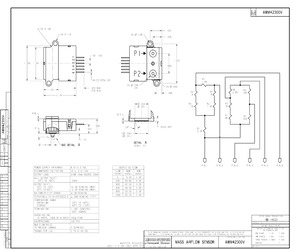
AWM42300V OF PAGE | REPLACES MI DRAWING NUMBER | RELEASE NO. PR-22391 ISSUE REVISIONS | cHECK CHECK PTC/CAD DRAWN 123 JAN 97 | cHeck GRT 2X R. 100 2X R.110 ta A I 5X .100 == VE2 1.200 1.09 ,-+F-- oS + oe a Lo _ co ee 2 Lj y Or ra 6X 1.025+.001 ~ .325 MAX < 99 270 MIN |} | | uo Zz 12 ~~) Ef. 14 ) } | / ial LN ZB .118 SEE DETAIL A . 900 8.0/15.0 VDC 10 + 0.01 VDC SINK 10mA SOURCE 20mA POWER SUPPLY (MIN/MAX) RECOMMENDED EXCITATION OUTPUT LOAD NULL OUTPUT SHIFT: 25C TO +85C OUTPUT SHIFT: 20mvV 25C TO -25C +2.5% READING (MAX) 25C TO 85C -2.5% READING (MAX) RAITOMETRICITY ERROR +.3% READING PEPEATABILITY & HYSTERESIS J|+.50% READING (TYP) TEMPERATURE RANGE OPERATING -25C 10 +85C STORAGE 40C TO +125C TERMINATION (. 100" CENTERS) 025" SQUARE SHOCK RATING (5 DROPS, EACH OF 6 AXES)|100g PEAK OVERPRESSURE [50 PSI MAX FLOW PULSE TO PREVENT DAMAGE 5 SLPM/SEC TORQUE PER LUG 2 10 6 IN LBS ANS | AWM42300V L 432 2X D.138 =_1 328 A q 337 680 R5 iL | 6K 2X B.090 -~V ? Rd R2 188 iP gv Ke (2) 2544 Rd gv
 1 Pages, 79 KB, Scan
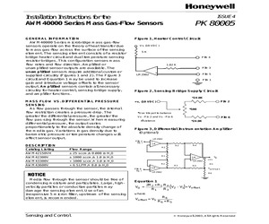
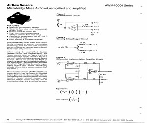
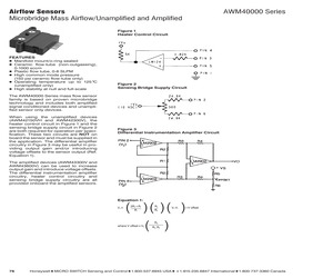
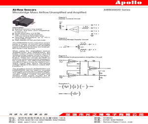
sing Bridge Supply Circuit The AWM40000 Series mass flow sensor family is based on proven microbridge technology and includes both amplified signal conditioned devices and unamplified sensor only devices. When using the unamplified devices (AWM42150VH and AWM42300V), the heater control circuit in Figure 1 and the sensing bridge supply circuit in Figure 2 are both required for operation per specification. These two circuits are NOT on board the sensor and must be supplied in the application. The differential amplifier circuitry in Figure 3 may be useful in providing output gain and/or introducing voltage offsets to the sensor output (Ref. Equation 1). Figure 3 Differential Instrumentation Amplifier Circuit The amplified devices (AWM43300V and AWM43600V) can be used to increase output gain and introduce voltage offsets. The differential instrumentation amplifier circuitry, heater control circuitry and sensing bridge supply circuitry are all provided onboard the amplified sensors. Equation 1: VoJ (
 3 Pages, 250 KB, Original
y at null and full-scale The AWM40000 Series mass flow sensor family is based on proven microbridge technology and includes both amplified signal conditioned devices and unampli- fied sensor only devices. When using the unamplified devices (AWM42150VH and AWM42300V), the heater control circuit in Figure 1 and the sensing bridge supply circuit in Figure 2 are both required for operation per speci- fication. These two circuits are NOT on boara the sensor and must be supplied in the application. The differential amplifier circuitry in Figure 3 may be useful in pro- viding output gain and/or introducing voltage offsets to the sensor output (Ref. Equation 1). The amplified devices (AWM43300V and AWM43600V) can be used to increase output gain and introduce voltage offsets. The differential instrumentation amplifier circuitry, heater control circuitry and sensing bridge supply circuitry are all provided onboard the amplified sensors. Figure 1 Heater Control Circuit +Vs PIN 4 1. 82K --VWAA0 PI 3 t+_-_ PI
 3 Pages, 145 KB, Scan
rimmed interchangeability * Accurate sensing of low pressure To view the entire mass airflow product portfolio, click here. AIRFLOW SENSORS, AMPLIFIED, AND UNAMPLIFIED AWM40000 SERIES TABLE 1. SPECIFICATIONS CHARACTERISTIC UNAMPLIFIED AMPLIFIED AWM42150VH AWM42300V AWM43300V AWM43600V-2 30 SCCM 1000 SCCM +1000 SCCM 0 SLPM to 6 SLPM -- -- nitrogen nitrogen 10 0.01 Vdc 10 0.01 Vdc 10.000 0.010 Vdc 10.000 0.010 Vdc 8.0 Vdc 15.0 Vdc 8.0 Vdc 15.0 Vdc 8.000 Vdc 15.000 Vdc 10.000 Vdc 15.000 Vdc 30 mW typ. 30 mW typ. 60 mW max. 75 mW max. 8.5 Vdc 1.5 mVdc at 25 SCCM 55.2 Vdc 2.0 mVdc at 1000 SCCM 5 Vdc 0.15 Vdc at 1000 SCCM 5 Vdc 0.15 Vdc at 6 SLPM Null output 0 mV 1 mV 0.0 mVdc 1.5 mVdc 1.0 mVdc 0.05 mVdc 1.000 Vdc 0.050 Vdc Null output shift (-25C to 85C) 0.20 mVdc 0.20 mVdc 0.025 Vdc max. 50 mVdc max. +2.5% reading max. -2.5% reading max. +2.5% reading,max. -2.5% reading max. -5.0% reading max. +6.0% reading max. -7.0% reading max. +7.0% reading max. Repeatability and hysteresis1 0.35% FSO typ. 0.50%
 6 Pages, 510 KB, Original
sing Bridge Supply Circuit The AWM40000 Series mass flow sensor family is based on proven microbridge technology and includes both amplified signal conditioned devices and unamplified sensor only devices. When using the unamplified devices (AWM42150VH and AWM42300V), the heater control circuit in Figure 1 and the sensing bridge supply circuit in Figure 2 are both required for operation per specification. These two circuits are NOT on board the sensor and must be supplied in the application. The differential amplifier circuitry in Figure 3 may be useful in providing output gain and/or introducing voltage offsets to the sensor output (Ref. Equation 1). Figure 3 Differential Instrumentation Amplifier Circuit The amplified devices (AWM43300V and AWM43600V) can be used to increase output gain and introduce voltage offsets. The differential instrumentation amplifier circuitry, heater control circuitry and sensing bridge supply circuitry are all provided onboard the amplified sensors. Equation 1: VoJ (
 4 Pages, 290 KB, Original
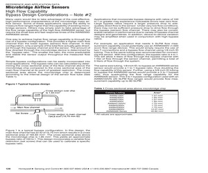
guration used with an AWM5104VN (20 SLPM flow range) would provide flow measurement capability up to 80 SLPM. Figure 1 Typical bypass design Table 1 Cross-sectional area above microbridge chip Catalog Listing AWM2100V AWM2300V AWM3100V AWM3300V AWM42150VH AWM42300V AWM43300V AWM43600V AWM5000 Series Area* 1.57 mm2 1.94 mm2 1.57 mm2 1.94 mm2 1.75 mm2 1.75 mm2 1.75 mm2 12.07 mm2 45.60 mm2 * All values are approximate. Figure 1 is a typical bypass configuration. In this design, the main flow channel has an ID of 15,75 mm which results in a cross sectional area of 194,83 mm2. The cross sectional area above the microbridge chip is 1,95 mm2. This yields an approximate bypass ratio of 100 to 1. This design incorporates a variable flow restriction (set screw) that can be used to calibrate a specific bypass ratio. 128 Honeywell 1 Sensing and Control 1 1-800-537-6945 USA 1 F1-815-235-6847 International 1 1-800-737-3360 Canada REFERENCE AND APPLICATION DATA Microbridge Airflow Sensors High Flow Capability B
 3 Pages, 218 KB, Original
sing Bridge Supply Circuit The AWM40000 Series mass flow sensor family is based on proven microbridge technology and includes both amplified signal conditioned devices and unamplified sensor only devices. When using the unamplified devices (AWM42150VH and AWM42300V), the heater control circuit in Figure 1 and the sensing bridge supply circuit in Figure 2 are both required for operation per specification. These two circuits are NOT on board the sensor and must be supplied in the application. The differential amplifier circuitry in Figure 3 may be useful in providing output gain and/or introducing voltage offsets to the sensor output (Ref. Equation 1). Figure 3 Differential Instrumentation Amplifier Circuit The amplified devices (AWM43300V and AWM43600V) can be used to increase output gain and introduce voltage offsets. The differential instrumentation amplifier circuitry, heater control circuitry and sensing bridge supply circuitry are all provided onboard the amplified sensors. Equation 1: VoJ (
 3 Pages, 258 KB, Original
e device to the next. Port style: SIGNAL CONDITIONING Unamplified (8.5 mV) Unamplified (54.7 mV) Amplified (1 Vdc to 5 Vdc) Amplified (1 Vdc to 5 Vdc) Manifold FLOW/PRESSURE RANGE 25 sccm 1000 sccm (1 SLPM) 1000 sccm (1 SLPM) + 6 SLPM REFERENCE AWM42150VH AWM42300V AWM43300V AWM43600V The rugged plastic package has been designed to withstand common mode pressures up to 50 psi, and the small sensing element allows 100 g of shock without compromising performance. The included "AMP" compatible connector provides reliable connection in many demanding applications. Each AWM5000 sensor contains circuitry which performs amplification, linearization, temperature compensation and gas calibration. A 1 Vdc to 5 Vdc linear output is possible for all listings regardless of flow range (5, 10, 15, or 20 SLPM) or calibration gas (nitrogen, carbon dioxide, nitrous oxide or argon). All calibration is performed by active laser. Signal conditioning: Port style: Amplified (1 Vdc to 5 Vdc) Threaded, 1/4 in NPT FLOW/PR
 108 Pages, 19402 KB, Original
ENCE AWM2100V AWM2200V AWM2300V SIGNAL CONDITIONING Unamplified (8.5 mV) Unamplified (54.7 mV) Amplified (1 Vdc to 5 Vdc) Amplified (1 Vdc to 5 Vdc) 10 Manifold www.honeywell.com/sensing FLOW/ REFERENCE PRESSURE RANGE 25 sccm AWM42150VH 1000 sccm (1 SLPM) AWM42300V 1000 sccm (1 SLPM) AWM43300V + 6 SLPM AWM43600V MASS AIRFLOW AWM5000 Series - High flow AWM5000 Series Microbridge Mass Airflow Sensors feature a Venturi type flow housing. They measure flow as high as 20 standard liters per minute (SLPM) while inducing a maximum pressure drop of 2.25 inches H2O. The microbridge chip is in direct contact with the flow stream, greatly reducing error possibilities due to orifice or bypass channel clogging. The rugged plastic package has been designed to withstand common mode pressures up to 50 psi, and the small sensing element allows 100 g of shock without compromising performance. The included "AMP" compatible connector provides reliable connection in demanding applications. Each AWM5000 sensor contain
 40 Pages, 3100 KB, Original
 CONDITIONING Unamplified (8.5 mV) Unamplified (54.7 mV) Amplified (1 Vdc to 5 Vdc) Amplified (1 Vdc to 5 Vdc) 10 Manifold www.honeywell.com/sensing FLOW/ PRESSURE RANGE 25 sccm 1000 sccm (1 SLPM) 1000 sccm (1 SLPM) REFERENCE + 6 SLPM AWM43600V AWM42150VH AWM42300V AWM43300V MASS AIRFLOW AWM5000 Series - High flow AWM5000 Series Microbridge Mass Airflow Sensors feature a Venturi type flow housing. They measure flow as high as 20 standard liters per minute (SLPM) while inducing a maximum pressure drop of 2.25 inches H2O. The microbridge chip is in direct contact with the flow stream, greatly reducing error possibilities due to orifice or bypass channel clogging. The rugged plastic package has been designed to withstand common mode pressures up to 50 psi, and the small sensing element allows 100 g of shock without compromising performance. The included "AMP" compatible connector provides reliable connection in demanding applications. Each AWM5000 sensor contains circuitry which performs amplificati
 73 Pages, 3661 KB, Original
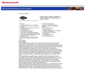
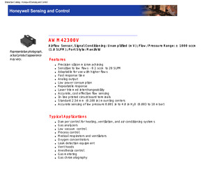
AWM42300V Airflow Sensor, Signal Conditioning: Unamplified (mV); Flow/Pressure Range: 1000 sccm (1.0 SLPM); Port Style: Manifold Actual product appearance may vary. Features Potential Applications Precision silicon micromachining Sensitive to low flows - 0.1 sccm to 20 SLPM Adaptable for use with higher flows Fast response time Analog output Low power consumption Repeatable response Laser trimmed interchangeability Accurate, cost effective flow sensing In-line printed circuit board terminals Standard 2.54 mm (0.100 in) mounting centers Accurate sensing of low pressure 0.001 in to 4.0 in H2O (0.003 to 10 mbar) Damper control for heating, ventilation, and air conditioning systems Gas analyzers Low vacuum control Process control Medical respirators and ventilators Oxygen concentrators Leak detection equipment Vent hoods Anesthesia control Gas metering Gas chromatography Description OPERATION The microbridge mass airflow sensor operates on the theory of heat transfer. Mass airflow is directed across
 4 Pages, 112 KB, Original
AWM42300V Representative photograph, actual product appearance may vary. Airflow Sensor, Signal Conditioning: Unamplified (mV); Flow/Pressure Range: 1000 sccm (1.0 SLPM); Port Style: Manifold Features Precision silicon micromachining Sensitive to low flows - 0.1 sccm to 20 SLPM Adaptable for use with higher flows Fast response time Analog output Low power consumption Repeatable response Laser trimmed interchangeability Accurate, cost effective flow sensing In-line printed circuit board terminals Standard 2.54 mm (0.100 in) mounting centers Accurate sensing of low pressure 0.001 in to 4.0 in H2O (0.003 to 10 mbar) Typical Applications Damper control for heating, ventilation, and air conditioning systems Gas analyzers Low vacuum control Process control Medical respirators and ventilators Oxygen concentrators Leak detection equipment Vent hoods Anesthesia control Gas metering Gas chromatography Interactive Catalog - Honeywell Sensing and Control Description OPERATION The microbridge mass airflow sen
 4 Pages, 35 KB, Original
6:00 4493 6.0 019 200 323 O17 1.52 -600 39.0 6.0 0.08 100 249 0.14 229 -1000 5.2 6.0 0.00 0 1.00 0.05 Notes: 1. NUMBers In BOLD type Indicate calibration type, mass flow of differential pressure. Tolerance values apply to calibration type only. AWM42150VH AWM42300V 15 Output Voltage vs Flow Output Voltage vs Flow > = o- 15 - - - - 60 a 1000 -750 -500 -250 oO 250 500 750 1000 a0 20 10 a 10 20 0 Mass-Flow (sccm) ___MassFlow (sccm) [Nominal - - - - -- Min/Max, | Nominal ------ Min Jak, AWM43300 AWM43600V Output Voltage vs Flow Output Voltage ve Flow o 5y-- ppp eepereceeseeeet 8 8 at pene e 5 3 aoe & BR a+ afte 6 no 34 Po - --- - 1 a 200 600 200 100 o 1 3 5 & Mase-Flow (sccm) Mass-Flow (sccm) Nominal + +--+ Min/Max. | | Naminal fe & S 2 aw) Bok BB im Ill Th Fe oZ 78 FB FG OR Z@ ol Hhit: FER PRIA AB 1006-1018 Bea: 518033 Bin: OT55-89279118/892 78699892 78860 +B: O755-89279285 fijdit: wew. apollosz, com Aisa: Sensor@apol losz. com
 3 Pages, 162 KB, Original