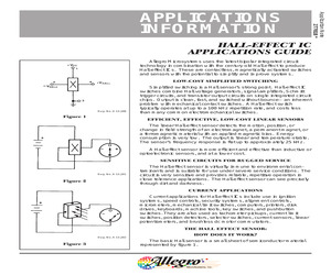
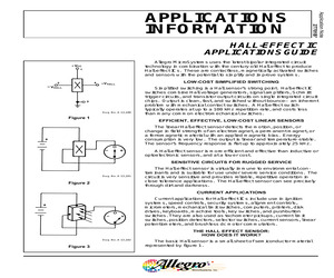
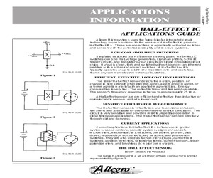
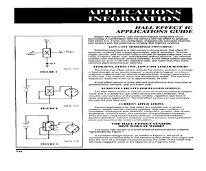
ctivating magnet approaches, the circuit shown in figure 20 could be used. Figure 20 7 HALL-EFFECT IC APPLICATIONS GUIDE When the Hall switch is OFF (insufficient magnetic flux to operate), about 12 mA of base current flows through the 1 k resistor to the 2N5812 transistor, thereby saturating it and shorting the base of the 2N3055 to ground, which keeps the load OFF. When a magnet is brought near the Hall switch, it turns ON, shorting the base of the 2N5812 to ground and turning it OFF. This allows: 12 V 56 = 210 mA of base current to flow to the 2N3055, which is enough to saturate it for any load current of 4 A or less. The Hall switch cannot source current to a load in its OFF state, but it is no problem to add a transistor that can. For example, consider using a 40669 triac to turn ON a 115 V or 230 V ac load. This triac would require about 80 mA of gate current to trigger it to the ON condition. This could be done with a 2N5811 PNP transistor, as shown below in figure 21. When th
 36 Pages, 421 KB, Original
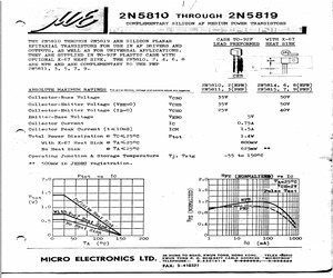
=5V IC=0 Collector-Emitter Saturation Voltage | VcE(sat)* 0.75 v Ic=500mA IB=50mA Base-Emitter Saturation Voltage VBE(sat)* 1.2 v Ic=500mA Ip=50mA Base-Emitter Voltage VBE * 0.6 1.1 v |iIg=500mA Vog=2 D.C. Current Gain tre * Io=2mA VcE=2V 2N5810, 1 60 200 2N5812, 3 150 500 2N5814, 5 60 120 2N5816, 7 100 200 2N5818, 9 . 150. 300 D.C. Current Gain Hrrm * I=500mA Vor=2V 2N5810, 1 45 o * 2N5812, 3 60 te ON5814, 5 20 2N5816, 7 25 2N5818, 9 25 Current Gain-Bandwidth Product fo Ic=50mA Ver=2V 2N5810, 1, 4, 5 100 MHz 2N5816, 7 120 MHz 2N5812, 3, 8, 9 135 MHz Collector-Base Capacitance Cob 15 pF | Vop=l0V Ig=0 f=1MHz Emitter-Base Capacitance Cib 55 pF | VeB=0.5V Ic=0 f=1MHz * Pulse Test : Pulse Width=0.3mS, Duty Cycle=1% v Vv Ic. 2.0 CE(sat) & VBE vs tC. . 250 Tae250C se Test 1.6 200 (MHz ) 0.8 100 0.4 50
 2 Pages, 164 KB, Scan
ctivating magnet approaches, the circuit shown in figure 20 could be used. Figure 20 7 HALL-EFFECT IC APPLICATIONS GUIDE When the Hall switch is OFF (insufficient magnetic flux to operate), about 12 mA of base current flows through the 1 k resistor to the 2N5812 transistor, thereby saturating it and shorting the base of the 2N3055 to ground, which keeps the load OFF. When a magnet is brought near the Hall switch, it turns ON, shorting the base of the 2N5812 to ground and turning it OFF. This allows: 12 V 56 = 210 mA of base current to flow to the 2N3055, which is enough to saturate it for any load current of 4 A or less. The Hall switch cannot source current to a load in its OFF state, but it is no problem to add a transistor that can. For example, consider using a 40669 triac to turn ON a 115 V or 230 V ac load. This triac would require about 80 mA of gate current to trigger it to the ON condition. This could be done with a 2N5811 PNP transistor, as shown below in figure 21. When th
 36 Pages, 790 KB, Original
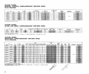
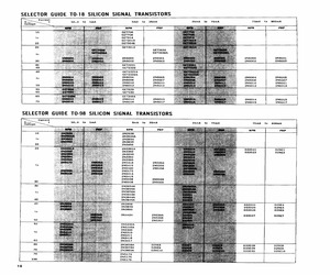
POSE COMPLEMENTARY PNP-NPN PAIRS T0-18 PACKAGE fre h @ 10V. 1M Pr FE ' z Type Vero @ 25C Ic! @ 2V, 2mA @ 2V, 500mA Max. NPN PNP ) (mW) (mA) Min. | Max. Min. fr Typical Package Specification (MHz, (pf) ) Outline No. Sheet No. 2N5810 2N5811 : 500 60 200 9.5 2N5812 2N5813 500 150 500 9.5 2N5814 2N5815 500 60 200 9.5 2N5816 2N5817 500 100 200 9.5 2N5818 2N5819 500 150 300 9.5 2N5820 2N5821 500 60 120 9.5 2N5822 2N5823 100 9.5 1 Steady State Collector Current SILICON SIGNAL ULTRA LOW NOISE COMPLEMENTARY PNP-NPN PAIRS hee N.F.2 Ceb @ 2V,100nA | @ 2V,10mA Typ. Max. @ 10V, 1MHz Package Specification Min. Min. (db) (db) (pf) Outline No. Sheet No. Pr Type Vceo @ 25C Ic! @ 2V, 104A NPN PNP (Vv) (mW) (mA) Min. 2N5998 2N5999 400 80 2N6008 2N6009 400 120 40.77 Steady State Collector Current 2N.F.Wide Band @ Vce = 5V, Ic =100uA, f = 10HZ to 1OKHZ, BW = 15.7 KHZ, Ro = 5K Q SILICON SIGNAL INDUSTRIAL COMPLEMENTARY PNP-NPN PAIRS T0-18 PACKAGE Min. Fee fr @ Pr (V) 10mA ton? tore? NF. Type Vceo T=25C Ic! @1V 1V | @ 2
 4 Pages, 1467 KB, Scan
ctivating magnet approaches, the circuit shown in figure 20 could be used. Figure 20 7 HALL-EFFECT IC APPLICATIONS GUIDE When the Hall switch is OFF (insufficient magnetic flux to operate), about 12 mA of base current flows through the 1 k resistor to the 2N5812 transistor, thereby saturating it and shorting the base of the 2N3055 to ground, which keeps the load OFF. When a magnet is brought near the Hall switch, it turns ON, shorting the base of the 2N5812 to ground and turning it OFF. This allows: 12 V = 210 mA 56 of base current to flow to the 2N3055, which is enough to saturate it for any load current of 4 A or less. The Hall switch cannot source current to a load in its OFF state, but it is no problem to add a transistor that can. For example, consider using a 40669 triac to turn ON a 115 V or 230 V ac load. This triac would require about 80 mA of gate current to trigger it to the ON condition. This could be done with a 2N5811 PNP transistor, as shown below in figure 21. When th
 36 Pages, 380 KB, Original
POSE COMPLEMENTARY PNP-NPN PAIRS T0-18 PACKAGE fre h @ 10V. 1M Pr FE ' z Type Vero @ 25C Ic! @ 2V, 2mA @ 2V, 500mA Max. NPN PNP ) (mW) (mA) Min. | Max. Min. fr Typical Package Specification (MHz, (pf) ) Outline No. Sheet No. 2N5810 2N5811 : 500 60 200 9.5 2N5812 2N5813 500 150 500 9.5 2N5814 2N5815 500 60 200 9.5 2N5816 2N5817 500 100 200 9.5 2N5818 2N5819 500 150 300 9.5 2N5820 2N5821 500 60 120 9.5 2N5822 2N5823 100 9.5 1 Steady State Collector Current SILICON SIGNAL ULTRA LOW NOISE COMPLEMENTARY PNP-NPN PAIRS hee N.F.2 Ceb @ 2V,100nA | @ 2V,10mA Typ. Max. @ 10V, 1MHz Package Specification Min. Min. (db) (db) (pf) Outline No. Sheet No. Pr Type Vceo @ 25C Ic! @ 2V, 104A NPN PNP (Vv) (mW) (mA) Min. 2N5998 2N5999 400 80 2N6008 2N6009 400 120 40.77 Steady State Collector Current 2N.F.Wide Band @ Vce = 5V, Ic =100uA, f = 10HZ to 1OKHZ, BW = 15.7 KHZ, Ro = 5K Q SILICON SIGNAL INDUSTRIAL COMPLEMENTARY PNP-NPN PAIRS T0-18 PACKAGE Min. Fee fr @ Pr (V) 10mA ton? tore? NF. Type Vceo T=25C Ic! @1V 1V | @ 2
 4 Pages, 1095 KB, Scan
POSE COMPLEMENTARY PNP-NPN PAIRS T0-18 PACKAGE fre h @ 10V. 1M Pr FE ' z Type Vero @ 25C Ic! @ 2V, 2mA @ 2V, 500mA Max. NPN PNP ) (mW) (mA) Min. | Max. Min. fr Typical Package Specification (MHz, (pf) ) Outline No. Sheet No. 2N5810 2N5811 : 500 60 200 9.5 2N5812 2N5813 500 150 500 9.5 2N5814 2N5815 500 60 200 9.5 2N5816 2N5817 500 100 200 9.5 2N5818 2N5819 500 150 300 9.5 2N5820 2N5821 500 60 120 9.5 2N5822 2N5823 100 9.5 1 Steady State Collector Current SILICON SIGNAL ULTRA LOW NOISE COMPLEMENTARY PNP-NPN PAIRS hee N.F.2 Ceb @ 2V,100nA | @ 2V,10mA Typ. Max. @ 10V, 1MHz Package Specification Min. Min. (db) (db) (pf) Outline No. Sheet No. Pr Type Vceo @ 25C Ic! @ 2V, 104A NPN PNP (Vv) (mW) (mA) Min. 2N5998 2N5999 400 80 2N6008 2N6009 400 120 40.77 Steady State Collector Current 2N.F.Wide Band @ Vce = 5V, Ic =100uA, f = 10HZ to 1OKHZ, BW = 15.7 KHZ, Ro = 5K Q SILICON SIGNAL INDUSTRIAL COMPLEMENTARY PNP-NPN PAIRS T0-18 PACKAGE Min. Fee fr @ Pr (V) 10mA ton? tore? NF. Type Vceo T=25C Ic! @1V 1V | @ 2
 3 Pages, 821 KB, Scan
ched requires 4 A and must turn ON when the activating magnet approaches, the circuit shown in Figure 20 could be used. When the Hall switch is OFF (insufficient magnetic flux to operate), about 12 mA of base current flows through the 1 kQ resistor to the 2N5812 transistor, thereby saturating it and shorting the base of the 2N3055 to ground, which keeps the load OFF. When a magnet is brought near the Hail switch, it turns ON, shorting the base of the 2N5812 to ground and turning it OFF. This allows: j2V =210mA 56 Q of base current to flow to the 2N3055, which is enough to saturate it for any load current of 4 A or less. The Hall switch cannot source current to a load in its OFF state, but it is no problem to add a transistor that can. For example, consider using a 40669 triac to turn ON a 115 V or 230 V ac load. This triac would require about 80 mA of gate current to trigger it to the ON condition. This could be done with a 2N5811 PNP transistor, as shown below in Figure 21. When the
 34 Pages, 1486 KB, Scan
85 2N5374 85 2N5783 76 2N5088 85 2N5375 85 2N5784 77 2N5089 85 2N5376 85 2N5785 77 2N5109 76 2N5377 85 2N5786 77 2N5114 111 2N5381 85 2N5794 82 2N5115 111 2N5383 85 2N5796 82 2N5116 111 2N5400 85 2N5810 85 2N5147 76 2N5401 2N5811 85 2N5148 76 2N5415 85 76 2N5812 86 2N5149 76 2N5416 76 2N5813 86 2N5150 76 2N5427 98 2N5816 86 2N5151 76 2N5428 98 2N5817 86 2N5152 76 2N5429 98 2N5818 86 2N5153 76 2N5430 98 2N5819 86 2N5154 76 2N5447 85 2N5822 86 2N5172 85 2N5457 112 2N5823 86 2N5179 81 2N5458 112 2N5830 86 94 * Special Order CE Closest equivalent (slight to significant electrical and/or mechanical differences) EM Exact electrical and mechanical. SE Exact mechanical equivalent, slight electrical differences. SM Exact electrical equivalent, slight mechanical differences. Ce tralr Semiconductor Carll. 194 Index/Cross Reference (Continued) Page Industry Part Number Central Part Number 2N5831 86 2N6071 CQ202-4B 2N5859 77 2N6071A CQ202-4BS Industry Part Number Central Part Number Code Page Industry Part Nu
 248 Pages, 89040 KB, Original
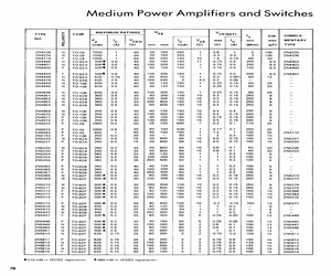
7 2N5450 N | To-92F | 5004] 0.8 30 50 150 50 2 0.8 0.1 100 12 2N5448 2N5451 N | TO-92F | 5004] 08 20 30 6600 50 2 1 0.1 100 12 2N5810 N TO-92F 625 0.75 25 60 200 2 2 0.75 0.5 100 15 2N5811 2N5811 P | TO-92F | 625 0.75 25 60 200 2 2 0.75 | 05 100 15 2N5810 2N5812 N | TO-92F | 625 0.75 25 | 150 500 2 2 0.75 | 0.5 135 15 2N5813 2N5813 P TO-92F 625 0.75 25 150 500 2 2 0.75 0.5 135 15 2N5812 2N5814 N | To-92F | 625 0.75 40 60 120 2 2 0.75 | 05 100 15 2N5815 2N5815 P | To-92F | 625 0.75 40 60 120 2 2 0.75 | 0.5 100 15 2N5814 310 mW in JEDEC registration 4360 mW in JEDEC registration
 1 Pages, 69 KB, Scan
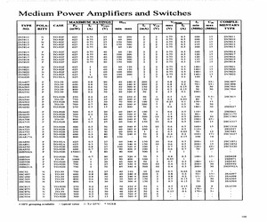
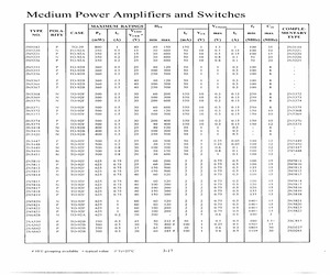
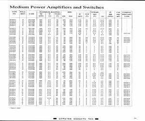
 TYPE |POLA-| CASE Py Ic Vero Ie | Veg | max Ic min | max | MENTARY NO. RITY (mW) (A) (Vv) min max (mA) (V) (A) | (MHz) | (Mz) TYPE 2N5810 N TO-92F 625 0.75 25 69 200 2 2 0.75 0.5 100 15 2N5811 2N5811 P TO-92F 625 0.75 25 60 200 2 2 0.75 0.5 100 15 2N5810 2N5812 N JO-92F 625 0.75 25 150 500 2 2 0.75 0.5 135 15 2N5813 2N5813 P TO-92F 625 0.75 25 150 500 2 2 0.75 0.5 135 15 2N5812 2N5814 N TO-92F 625 0.75 40 60 120 2 2 0.75 0.5 100 15 2N5815 2N5815 P TO-92F 625 0.75 40 60 120 2 2 0.75 0.5 100 15 2N5814 2N5816 N TO-92F 625 0.75 40 100 =200 2 2 0.75 0.5 120 15 2N5817 2N5817 P TO-92F 625 0.75 40 100 200 2 2 0.75 0.5 120 15 2N5816 2N5818 N TO-92F 625 0.75 40 150 6-300 2 2 0.75 0.5 135 15 2N5819 2N5819 P TO-92F 625 0.75 40 150 300 2 2 0.75 0.5 135 15 2N5818 2N5820 N TO-92F 625 1 60 60 120 2 2 0.75 0.5 140+ 15 2N5821 2N5821 P TO-92F 625 1 60 60 120 2 2 0.75 0.5 140+ 15 2N5820 2N5822 N TO-92F 625 1 60 100 200 2 2 0.75 0.5 140+ 15 2N5823 2N5823 P TO-92F 625 1 60 100 200 2 2 0.75 0.5 140+ 15 2N
 1 Pages, 74 KB, Scan
POSE COMPLEMENTARY PNP-NPN PAIRS T0-18 PACKAGE fre h @ 10V. 1M Pr FE ' z Type Vero @ 25C Ic! @ 2V, 2mA @ 2V, 500mA Max. NPN PNP ) (mW) (mA) Min. | Max. Min. fr Typical Package Specification (MHz, (pf) ) Outline No. Sheet No. 2N5810 2N5811 : 500 60 200 9.5 2N5812 2N5813 500 150 500 9.5 2N5814 2N5815 500 60 200 9.5 2N5816 2N5817 500 100 200 9.5 2N5818 2N5819 500 150 300 9.5 2N5820 2N5821 500 60 120 9.5 2N5822 2N5823 100 9.5 1 Steady State Collector Current SILICON SIGNAL ULTRA LOW NOISE COMPLEMENTARY PNP-NPN PAIRS hee N.F.2 Ceb @ 2V,100nA | @ 2V,10mA Typ. Max. @ 10V, 1MHz Package Specification Min. Min. (db) (db) (pf) Outline No. Sheet No. Pr Type Vceo @ 25C Ic! @ 2V, 104A NPN PNP (Vv) (mW) (mA) Min. 2N5998 2N5999 400 80 2N6008 2N6009 400 120 40.77 Steady State Collector Current 2N.F.Wide Band @ Vce = 5V, Ic =100uA, f = 10HZ to 1OKHZ, BW = 15.7 KHZ, Ro = 5K Q SILICON SIGNAL INDUSTRIAL COMPLEMENTARY PNP-NPN PAIRS T0-18 PACKAGE Min. Fee fr @ Pr (V) 10mA ton? tore? NF. Type Vceo T=25C Ic! @1V 1V | @ 2
 3 Pages, 1056 KB, Scan
.1 100 12 2N5447 2N5450 N TO-92F 500 0.8 30 50 150 50 2 0.8 0.1 100 12 2N5448 2N5451 N TO-92F 500 0.8 20 30 600 50 2 l 0.1 100 12 - 2N5810 N TO-92F 625 0.75 25 60 200 2 2 0.75 0.5 100 15 2N5811 2N5811 P TO-92F 625 0.75 25 60 200 2 2 0.75 0.5 100 15 2N5810 2N5812 N TO-92F 625 0.75 25 150 500 2 2 0.75 0.5 135 15 2N5813 2NS813 P TO-92F 625 0.75 25 150 6500 2 2 0.75 0.5 135 15 2N5812 2N5814 N TO-92F 625 0.75 40 60 120 2 2 0.75 0.5 100 15 2N5815 2NS815 P TO-92F 625 0.75 40 60 120 2 2 0.75 0.5 100 15 2N5814 2N5816 N TO-92F 625 0.75 40 100 =200 2 2 0.75 0.5 120 15 2N5817 2NS817 P TO-92F 625 0.75 40 100 200 2 2 0.75 0.5 120 15 2N5816 2N5818 N TO-92F 625 0.75 40 150 300 2 2 0.75 0.5 135 15 2N5819 2N5819 P TO-92F 625 0.75 40 150 = 300 2 2 0.75 0.5 135 15 2N5818 2N5820 N TO-92F 625 1 60 60 120 2 2 0.75 0.5 140+ 15 2N5821 2N5821 P TO-92F 625 1 60 60 120 2 2 0.75 0.8 140+ 15 2N5826 2N5822 N TO-92F 625 j 60 100 =200 2 2 0.75 0.5 140+ 15 2N5823 2N5823 P TO-92F 625 } 60 100 200 2 2 0.75 0.5 140+ 15
 1 Pages, 153 KB, Scan
.1 100 12 2N5447 2N5450 N TO-92F 500 0.8 30 50 150 50 2 0.8 0.1 100 12 2N5448 2N5451 N TO-92F 500 0.8 20 30 600 50 2 i 0.1 100 12 - 2N5810 N TO-92F 625 0.75 25 60 200 2 2 0.75 0.5 100 15 2N5811 2N5811 P TO-92F 625 0.75 25 60 200 2 2 0.75 0.5 100 15 2N5810 2N5812 N TO-92F 625 0.75 25 150 500 2 2 0.75 0.5 135 15 2N5813 2N5813 Pp TO-92F 625 0.75 25 150 500 2 2 0.75 0.5 135 15 2N5812 2N5814 N TO-92F 625 0.75 40 60 120 2 2 0.75 0.5 100 18 2N5815 2N5815 P TO-92F 625 0.75 40 60 120 2 2 0.75 0.5 100 15 2N5814 2N5816 N TO-92F 625 0.75 40 100 200 2 2 0.75 0.5 120 15 2N5817 2N5817 P TO-92F 625 0.75 40 100 200 2 2 0.75 0.5 120 15 2N5816 2N5818 N TO-92F 625 0.75 40 150 300 2 2 0.75 0.5 135 18 2N5819 2N5819 P TO-92F 625 0.75 40 150 300 2 2 0.75 0.5 135 15 2N5818 2N5820 N TO-92F 625 1 60 60 120 2 2 0.75 0.5 140+ 15 2N5821 2N5821 P TO-92F 625 1 60 60 120 2 2 0.75 0.5 140+ 15 2N5820 2N5822 N TO-92F 625 1 60 100 200 2 2 0.75 0.5 140+ 15 2N5823 2N5823 P TO-92F 625 1 60 100 200 2 2 0.75 0.5 140+ 15 2N58
 1 Pages, 119 KB, Scan
POSE COMPLEMENTARY PNP-NPN PAIRS T0-18 PACKAGE fre h @ 10V. 1M Pr FE ' z Type Vero @ 25C Ic! @ 2V, 2mA @ 2V, 500mA Max. NPN PNP ) (mW) (mA) Min. | Max. Min. fr Typical Package Specification (MHz, (pf) ) Outline No. Sheet No. 2N5810 2N5811 : 500 60 200 9.5 2N5812 2N5813 500 150 500 9.5 2N5814 2N5815 500 60 200 9.5 2N5816 2N5817 500 100 200 9.5 2N5818 2N5819 500 150 300 9.5 2N5820 2N5821 500 60 120 9.5 2N5822 2N5823 100 9.5 1 Steady State Collector Current SILICON SIGNAL ULTRA LOW NOISE COMPLEMENTARY PNP-NPN PAIRS hee N.F.2 Ceb @ 2V,100nA | @ 2V,10mA Typ. Max. @ 10V, 1MHz Package Specification Min. Min. (db) (db) (pf) Outline No. Sheet No. Pr Type Vceo @ 25C Ic! @ 2V, 104A NPN PNP (Vv) (mW) (mA) Min. 2N5998 2N5999 400 80 2N6008 2N6009 400 120 40.77 Steady State Collector Current 2N.F.Wide Band @ Vce = 5V, Ic =100uA, f = 10HZ to 1OKHZ, BW = 15.7 KHZ, Ro = 5K Q SILICON SIGNAL INDUSTRIAL COMPLEMENTARY PNP-NPN PAIRS T0-18 PACKAGE Min. Fee fr @ Pr (V) 10mA ton? tore? NF. Type Vceo T=25C Ic! @1V 1V | @ 2
 4 Pages, 1432 KB, Scan