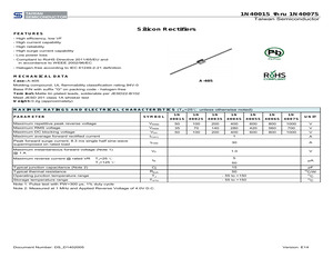
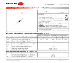
1N4007S Taiwan Semiconductor CREAT BY ART Silicon Rectifiers FEATURES - High efficiency, low VF - High current capability - High reliability - High surge current capability - Low power loss - Compliant to RoHS Directive 2011/65/EU and in accordance to WEEE 2002/96/EC - Halogen-free according to IEC 61249-2-21 definition MECHANICAL DATA Case: A-405 A-405 Molding compound, UL flammability classification rating 94V-0 Base P/N with suffix "G" on packing code - halogen-free Terminal: Matte tin plated leads, solderable per JESD22-B102 Meet JESD 201 class 1A whisker test Weight: 0.2g (approximately) MAXIMUM RATINGS AND ELECTRICAL CHARACTERISTICS (TA=25 unless otherwise noted) PARAMETER SYMBOL 1N 1N 1N 1N 1N 1N 1N 4001S 4002S 4003S 4004S 4005S 4006S 4007S UNIT Maximum repetitive peak reverse voltage VRRM 50 100 200 400 600 800 1000 V Maximum RMS voltage VRMS 35 70 140 280 420 560 700 V Maximum DC blocking voltage VDC 50 100 200 400 600 800 1000 V Maximum average forward rectified current IF(AV) 1 A Peak
 5 Pages, 196 KB, Original
1N4007S Taiwan Semiconductor CREAT BY ART Silicon Rectifiers FEATURES - High efficiency, low VF - High current capability - High reliability - High surge current capability - Low power loss - Compliant to RoHS Directive 2011/65/EU and in accordance to WEEE 2002/96/EC - Halogen-free according to IEC 61249-2-21 definition MECHANICAL DATA Case: A-405 A-405 Molding compound, UL flammability classification rating 94V-0 Base P/N with suffix "G" on packing code - halogen-free Terminal: Matte tin plated leads, solderable per JESD22-B102 Meet JESD 201 class 1A whisker test Weight: 0.2g (approximately) MAXIMUM RATINGS AND ELECTRICAL CHARACTERISTICS (TA=25 unless otherwise noted) PARAMETER SYMBOL 1N 1N 1N 1N 1N 1N 1N 4001S 4002S 4003S 4004S 4005S 4006S 4007S UNIT Maximum repetitive peak reverse voltage VRRM 50 100 200 400 600 800 1000 V Maximum RMS voltage VRMS 35 70 140 280 420 560 700 V Maximum DC blocking voltage VDC 50 100 200 400 600 800 1000 V Maximum average forward rectified current IF(AV) 1 A Peak
 4 Pages, 193 KB, Original
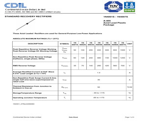
1N4007S A-405 Axial Lead Plastic Package These Axial Leaded Rectifiers are used for General-Purpose Low-Power Applications ABSOLUTE MAXIMUM RATINGS (Ta = 25C) 1N 1N 1N 1N 1N 1N 1N UNIT 4001S 4002S 4003S 4004S 4005S 4006S 4007S DESCRIPTION SYMBOL Peak Repetitive Reverse Voltage Working Peak Reverse Voltage DC Blockng Voltage VRRM VRWM VR 50 100 200 400 600 800 1000 V Non-Repetitive Peak Reverse Voltage (halfwave, single phase, 60Hz) VRSM 60 120 240 480 720 1000 1200 V VR(RMS) 35 70 140 280 420 560 700 V RMS Reverse Voltage Average Rectified Current at Half Wave 0.375" Lead Length at Ta = 75C Non-Repetitive Peak Surge Current 8.3ms single half sine-wave superimposed on rated Load Thermal Resistance from Junction to Ambient in free air StorageTemperature Range Operating Junction Temperature IO 1.0 A IFSM 30 A Rth (j-a) 50 C/W Tstg - 65 to +175 C Tj -65 to +175 C 1N4001_07Rev020606D Continental Device India Limited Data Sheet Page 1 of 5 1N4001S - 1N4007S A-405 Axial Lead Plastic Package
 5 Pages, 134 KB, Original
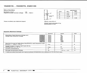
1N4007S, EM513S Silicon Rectifiers | Millimeters Nominal current 1A Cc 4 . Dim. Min. Max. Repetitive peak reverse voltage 100... 1600 V | ll. Be A 4.07 5.20 A B 2.04 271 \ Cathode Mark Cc 27.94 Cc D 0.71 0.86 | of. o | These rectifiers are delivered taped. Plastic case DO-41 Weight approximately 0.3 g Dimensions in mm Absolute Maximum Ratings Symbol Value Unit Repetitive Peak Reverse Voltage and 1N4001S VarmM 50 Vv Surge Peak Reverse Voltage 1N4002S VarRM 100 Vv 1N4003S Vero 200 Vv 1N4004S Varo 400 Vv 1N4005S Ver 600 Vv 1N4006S Ver 800 Vv 1N4007S VaR 1000 Vv EM513S VaRM 1600 Vv Nominal Current at Halfe Wave Rectification with Resistive Load at Tamb = 65to +75C lrav sh A Surge Forward Current, Half Cycle 50 Hz, starting from T; = 25 C lesm 30 A Junction Temperature Tj 125 C Storage Temperature Range Ts 65 to + 125 C Valid provided that leads are kept at ambient temperature at a distance of 10 mm from case. 2 MS 4682711 0003869 0751N4001S. ..1N4007S, EM513S Characteristics
 3 Pages, 73 KB, Scan
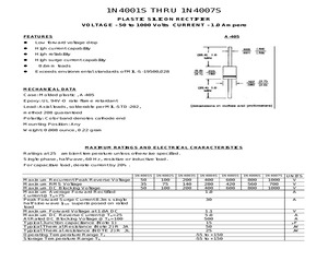
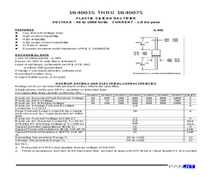
1N4007S PLASTIC SILICON RECTIFIER VOLTAGE - 50 to 1000 Volts CURRENT - 1.0 Ampere A-405 FEATURES l Low forward voltage drop l High current capability l High reliability l High surge current capability l l 0.6mm leads Exceeds environmental standards of MIL-S-19500/228 MECHANICAL DATA Case: Molded plastic , A-405 Epoxy: UL 94V-O rate flame retardant Lead: Axial leads, solderable per MIL-STD-202, method 208 guaranteed Polarity: Color band denotes cathode end Mounting Position: Any Weight: 0.008 ounce, 0.22 gram MAXIMUM RATINGS AND ELECTRICAL CHARACTERISTICS Ratings at 25 ambient temperature unless otherwise specified. Single phase, half wave, 60 Hz, resistive or inductive load. For capacitive load, derate current by 20%. 1N4001S 1N4002S 1N4003S 1N4004S 1N4005S 1N4006S 1N4007S Maximum Recurrent Peak Reverse Voltage Maximum RMS Voltage Maximum DC Blocking Voltage Maximum Average Forward Rectified Current @TA=75 Peak Forward Surge Current 8.3ms single half sine-wave IFSM superimposed on ra
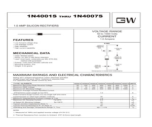
 3 Pages, 137 KB, Original
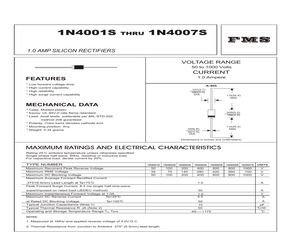
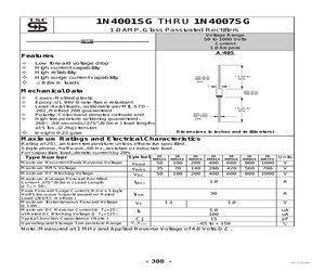
1N4007S 1.0 AMP SILICON RECTIFIERS VOLTAGE RANGE 50 to 1000 Volts CURRENT 1.0 Ampere FEATURES * Low forward voltage drop * High current capability * High reliability * High surge current capability A-405 .107(2.7) .080(2.0) DIA. 1.0(25.4) MIN. MECHANICAL DATA * Case: Molded plastic * Epoxy: UL 94V-0 rate flame retardant * Lead: Axial leads, solderable per MIL-STD-202, method 208 guranteed * Polarity: Color band denotes cathode end * Mounting position: Any * Weight: 0.34 grams .205(5.2) .166(4.2) 1.0(25.4) MIN. .025(.6) .021(.5) DIA. Dimensions in inches and (millimeters) MAXIMUM RATINGS AND ELECTRICAL CHARACTERISTICS Rating 25 C ambient temperature uniess otherwies specified. Single phase half wave, 60Hz, resistive or inductive load. For capacitive load, derate current by 20%. TYPE NUMBER Maximum Recurrent Peak Reverse Voltage Maximum RMS Voltage Maximum DC Blocking Voltage Maximum Average Forward Rectified Current 1N4001S 50 35 50 1N4002S 1N4003S 100 70 100 1N4004S 1N4005S 400 280 400 600 420 60
 2 Pages, 47 KB, Original
1N4007S SILICON RECTIFIERS Reverse Voltage - 50 to 1000 Volts Forward Current - 1.0 Ampere Features * * * * * Low forward voltage drop High current capability High reliability High surge current capability &0.6mm leads Mechanical Data * Cases: Molded plastic. * Lead: Axial leads, solderable per MIL-STD -202, method 208 guaranteed * Polarity: Color band denotes cathode end * High temperature soldering guaranteed: 250oC/ 10 seconds/ 0.375", (9.5 mm) lead lengths at 5 lbs., (2.3 kg) tension Absolute Maximum Ratings and Characteristics o Rating at 25 C ambient temperature unless otherwise specified. Single phase, half wave, 60 Hz, resistive or inductive load. For capacitive load, derate current by 20%. Symbols 1N 1N 1N 1N 1N 1N 1N 4001S 4002S 4003S 4004S 4005S 4006S 4007S Units Maximum recurrent peak reverse voltage VRRM 50 100 200 400 600 800 1000 V Maximum RMS voltage VRMS 35 70 140 280 420 560 700 V Maximum DC blocking voltage VDC 50 100 200 400 600 800 1000 V Maximum average forward rectified cur
 2 Pages, 240 KB, Original
1N4007S 1.0 AMP SILICON RECTIFIERS VOLTAGE RANGE 50 to 1000 Volts CURRENT 1.0 Ampere FEATURES * Low forward voltage drop * Low leakage current * High reliability * High current capability A-405 .107(2.7) .080(2.0) DIA. 1.0(25.4) MIN. MECHANICAL DATA * Case: Molded plastic * Epoxy: UL 94V-0 rate flame retardant * Lead: Axial leads, solderable per MIL-STD-202, method 208 guranteed * Polarity: Color band denotes cathode end * Mounting position: Any * Weight: 0.22 grams .205(5.2) .166(4.2) 1.0(25.4) MIN. .025(.6) .021(.5) DIA. Dimensions in inches and (millimeters) MAXIMUM RATINGS AND ELECTRICAL CHARACTERISTICS Rating 25 C ambient temperature uniess otherwies specified. Single phase half wave, 60Hz, resistive or inductive load. For capacitive load, derate current by 20%. TYPE NUMBER Maximum Recurrent Peak Reverse Voltage Maximum RMS Voltage Maximum DC Blocking Voltage Maximum Average Forward Rectified Current 1N4001S 1N4002S 1N4003S 1N4004S 1N4005S 1N4006S 1N4007S UNITS 50 35 50 100 70 1
 2 Pages, 131 KB, Original
1N4007S GENERAL PURPOSE PLASTIC SILICON RECTIFIER 50 to 1000 VOLTS 1.0 AMPERE REVERSE VOLTAGE: FORWARD CURRENT: FEATURES * Low forward voltage drop * High current capability * High reliability * High forward surge current capability MECHANICAL DATA Case: Molded plastic, A-405 Epoxy: UL 94V-O rate flame retardant Lead: Axial leads, solderable per MIL-STD-202, method 208 guaranteed Polarity: Color band denotes cathode end Mounting position: Any Weight: 0.008ounce, 0.22gram Dimensions in inches and (millimeters) Maximum Ratings and Electrical Characteristics Ratings at 25 ambient temperature unless otherwise specified. Single phase, half wave, 60H Z, resistive or inductive load. For capacitive load, derate current by 20%. Symbols 1N4001S 1N4002S 1N4003S 1N4004S 1N4005S 1N4006S 1N4007S Units Maximum Recurrent Peak Reverse Voltage VRRM 50 100 200 400 600 800 1000 Volts Maximum RMS Voltage VRMS 35 70 140 280 420 560 700 Volts Maximum DC Blocking Voltage VDC 50 100 200 400 600 800 1000 Volt
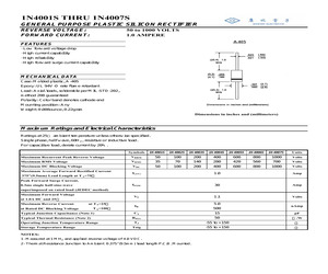 2 Pages, 137 KB, Original
1N4007SGP 1.0 Amp. Glass Passivated Junction Rectifier Current 1.0 A at 50 C Voltage 200V to 1000 V A-405 FEATURES Glass passivated chip junction High reliability Cavity-free glass-passivated junction Low forward voltage drop Low leakage current, typical IR less than 0.1 A High forward surge capability Solder dip 260C, 10s Component in accordance to RoHS 2011/65/EU and WEEE 2002/96/EC MECHANICAL DATA Case: A-405. Epoxy meets UL 94V-0 flammability rating. Polarity: Color band denotes cathode end Terminals : Matte tin plated leads, solderable per MIL-STD-750 Method 2026, J-STD-002 and JESD22-B102. Consumer grade, meets JESD 201 class 1A whisker test. TYPICAL APPLICATIONS Used in general purpose rectification of power supplies, inverters, converters and freewheeling diodes application Maximun Ratings and Electrical Characteristics at 25C VRRM 1N 1N 1N 1N 1N 4003SGP 4004SGP 4005SGP 4006SGP 4007SGP Maximum Recurrent Peak Reverse Voltage (V) 200 400 600 800 1000 VRMS Maximum RMS Voltage (V) 140 280 420
 4 Pages, 268 KB, Original
1N4007S 1.0 AMP SILICON RECTIFIERS VOLTAGE RANGE 50 to 1000 Volts CURRENT 1.0 Ampere FEATURES * Low forward voltage drop * Low leakage current * High reliability * High current capability A-405 .107(2.7) .080(2.0) DIA. 1.0(25.4) MIN. MECHANICAL DATA * Case: Molded plastic * Epoxy: UL 94V-0 rate flame retardant * Lead: Axial leads, solderable per MIL-STD-202, method 208 guranteed * Polarity: Color band denotes cathode end * Mounting position: Any * Weight: 0.22 grams .205(5.2) .166(4.2) 1.0(25.4) MIN. .025(.6) .021(.5) DIA. Dimensions in inches and (millimeters) MAXIMUM RATINGS AND ELECTRICAL CHARACTERISTICS Rating 25 C ambient temperature uniess otherwies specified. Single phase half wave, 60Hz, resistive or inductive load. For capacitive load, derate current by 20%. TYPE NUMBER Maximum Recurrent Peak Reverse Voltage Maximum RMS Voltage Maximum DC Blocking Voltage Maximum Average Forward Rectified Current 1N4001S 1N4002S 1N4003S 1N4004S 1N4005S 1N4006S 1N4007S UNITS 50 35 50 100 70 1
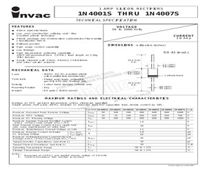
 2 Pages, 49 KB, Original
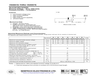
1N4007S TECHNICAL SPECIFICATION FEATURES VOLTAGE 50 to 1000 Volts 0.6mm diameter leads Low cost construction utilizing void - free moulded plastic technique CURRENT 1.0 Amp Plastic package has Underwriters Laboratories Flammability Classification 94V-0 Diffused junction DIMENSIONS - millimeters (inches) High surge current capability Low leakage DO-41 (mod.) High temperature soldering capability : 250C/10 seconds/9.5mm (.375in.) lead length at 2.3kg (5lb) tension Easily cleaned with Freon, Alcohol, Chlorothene and other similar solvents 25.4 (1.0) min. 2.7 (.107) 2.0 (.080) MECHANICAL DATA 5.2 (.205) 4.1 (.160) Case : JEDEC DO-41, moulded plastic with modified terminal diameter. Terminals : Plated axial leads, solderable per MIL-STD-202, Method 208. Polarity : Colour band denotes cathode end. Mounting Position : Any Weight : 0.3 grams (0.012 ounce) Cathode Band 25.4 (1.0) min. .64 (.025) .53 (.021) MAXIMUM RATINGS AND ELECTRICAL CHARACTERISTICS Ratings at 25C ambient temperature unless otherwise s
 2 Pages, 33 KB, Original
1N4007S PLASTIC SILICON RECTIFIER VOLTAGE - 50 to 1000 Volts CURRENT - 1.0 Ampere FEATURES l Low forward voltage drop l High current capability A-405 l l l High reliability High surge current capability r 0.6mm leads l Exceeds environmental standards of MIL-S-19500/228 MECHANICAL DATA Case: Molded plastic , A-405 Epoxy: UL 94V-O rate flame retardant Lead: Axial leads, solderable per MIL-STD-202, method 208 guaranteed Polarity: Color band denotes cathode end Mounting Position: Any Weight: 0.008 ounce, 0.22 gram MAXIMUM RATINGS AND ELECTRICAL CHARACTERISTICS Ratings at 25 J ambient temperature unless otherwise specified. Single phase, half wave, 60 Hz, resistive or inductive load. For capacitive load, derate current by 20%. 1N4001S 1N4002S 1N4003S 1N4004S 1N4005S 1N4006S 1N4007S Maximum Recurrent Peak Reverse Voltage Maximum RMS Voltage Maximum DC Blocking Voltage Maximum Average Forward Rectified Current @TA=75 J Peak Forward Surge Current 8.3ms single half sine-wave IFSM superimposed
 2 Pages, 31 KB, Original
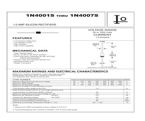
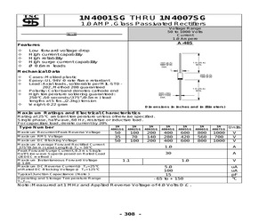
1N4007SG 1.0 AMP. Glass Passivated Rectifiers Voltage Range 50 to 1000 Volts Current 1.0 Ampere A-405 Features a Low forward voltage drop a High current capability a High reliability aHigh surge current capability a0.6mm leads Mechanical Data a Cases: Molded plastic a Epoxy: UL 94V-0 rate flame retardant a Lead: Axial leads, solderable per MIL-STD202, Method 208 guaranteed a Polarity: Color band denotes cathode end a High temperature soldering guaranteed: 260/10 seconds/.375",(9.5mm) lead lengths at 5 lbs.,(2.3kg) tension aWeight: 0.22 gram Dimensions in inches and (millimeters) Maximum Ratings and Electrical Characteristics Rating at 25ambient temperature unless otherwise specified. Single phase, half wave, 60 Hz, resistive or inductive load. For capacitive load, derate current by 20% 1N 1N Symbol 4001SG Type Number 4002SG Maximum Recurrent Peak Reverse Voltage Maximum RMS Voltage Maximum DC Blocking Voltage Maximum Average Forward Rectified Current .375" (9.5mm) Lead Length @TA = 50 Peak Forwar
 2 Pages, 49 KB, Original
1N4007SG 1.0 AMP. Glass Passivated Rectifiers Voltage Range 50 to 1000 Volts Current 1.0 Ampere A-405 Features a a a a a Low forward voltage drop High current capability High reliability High surge current capability O 0.6mm leads Mechanical Data a a a a a a Cases: Molded plastic Epoxy: UL 94V-0 rate flame retardant Lead: Axial leads, solderable per MIL-STDLead: 202, Method 208 guaranteed Polarity: Color band denotes cathode end High temperature soldering guaranteed: 250C/10 seconds/.375",(9.5mm) lead lengths at 5 lbs.,(2.3kg) tension Weight: 0.22 gram Dimensions in inches and (millimeters) Maximum Ratings and Electrical Characteristics Rating at 25C ambient temperature unless otherwise specified. Single phase, half wave, 60 Hz, resistive or inductive load. For capacitive load, derate current by 20% Type Number Maximum Recurrent Peak Reverse Voltage Maximum RMS Voltage Maximum DC Blocking Voltage Maximum Average Forward Rectified Current .375"(9.5mm) Lead Length @TA = 50C Peak Forward Surge Curre
 2 Pages, 44 KB, Original