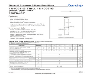
1N4007-G Voltage: 50 to 1000 V Current: 1.0 A RoHS Device Features DO-41 -Low cost construction. -Fast forward voltage drop. -Low reverse leakage. -High forward surge current capability. 1.0(25.40) Min. O -High soldering temperature guarantee: 260 C/10 seconds, 0.375"(9.5mm) lead length at 5lbs(2.3kg) tension. 0.205(5.20) 0.160(4.20) Mechanical data 0.107(2.70) 0.080(2.00) -Case: transfer molded plastic, DO-41 1.0(25.40) Min. -Epoxy: UL 94V-0 rate flame retardant -Polarity: Indicated by cathode band -Lead: Plated axial lead, solderable per MIL-STD202E, method 208C 0.034(0.90) 0.028(0.70) -Mounting position: Any Dimensions in inches and (millimeter) -Weight: 0.012ounce, 0.33 grams Electrical Characteristics (at TA=25C unless otherwise noted) Ratings at 25C ambient temperature unless otherwise specified. Single phase, half wave, 60Hz, resistive or inductive load. For capacitive load derate current by 20%. Symbol 1N4001 -G 1N4002 -G 1N4003 -G 1N 4004 -G 1N4005 -G 1N4006 -G 1N4007 -G Unit Maximum Rep
 2 Pages, 53 KB, Original
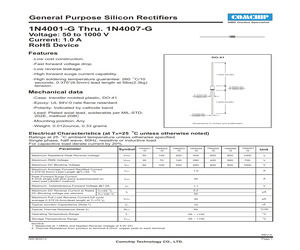
1N4007-G Voltage: 50 to 1000 V Current: 1.0 A RoHS Device Features DO-41 -Low cost construction. -Fast forward voltage drop. -Low reverse leakage. -High forward surge current capability. 1.0(25.40) Min. O -High soldering temperature guarantee: 260 C/10 seconds, 0.375"(9.5mm) lead length at 5lbs(2.3kg) tension. 0.205(5.20) 0.160(4.20) Mechanical data 0.107(2.70) 0.080(2.00) -Case: transfer molded plastic, DO-41 1.0(25.40) Min. -Epoxy: UL 94V-0 rate flame retardant -Polarity: Indicated by cathode band -Lead: Plated axial lead, solderable per MIL-STD202E, method 208C 0.034(0.90) 0.028(0.70) -Mounting position: Any Dimensions in inches and (millimeter) -Weight: 0.012ounce, 0.33 grams O Electrical Characteristics (at TA=25 C unless otherwise noted) O Ratings at 25 C ambient temperature unless otherwise specified. Single phase, half wave, 60Hz, resistive or inductive load. For capacitive load derate current by 20%. Symbol 1N4001 -G 1N4002 -G 1N4003 -G 1N 4004 -G 1N4005 -G 1N4006 -G 1N4007 -G Unit Maxim
 2 Pages, 31 KB, Original
1N4007-G Voltage: 50 to 1000 V Current: 1.0 A RoHS Device Features DO-41 -Low cost construction. -Fast forward voltage drop. -Low reverse leakage. -High forward surge current capability. 1.0(25.40) Min. O -High soldering temperature guarantee: 260 C/10 seconds, 0.375"(9.5mm) lead length at 5lbs(2.3kg) tension. 0.205(5.20) 0.160(4.20) Mechanical data 0.107(2.70) 0.080(2.00) -Case: transfer molded plastic, DO-41 1.0(25.40) Min. -Epoxy: UL 94V-0 rate flame retardant -Polarity: Indicated by cathode band -Lead: Plated axial lead, solderable per MIL-STD202E, method 208C 0.034(0.90) 0.028(0.70) -Mounting position: Any Dimensions in inches and (millimeter) -Weight: 0.012ounce, 0.33 grams Electrical Characteristics (at TA=25C unless otherwise noted) Ratings at 25C ambient temperature unless otherwise specified. Single phase, half wave, 60Hz, resistive or inductive load. For capacitive load derate current by 20%. Symbol 1N4001 -G 1N4002 -G 1N4003 -G 1N 4004 -G 1N4005 -G 1N4006 -G 1N4007 -G Unit Maximum Rep
 3 Pages, 58 KB, Original
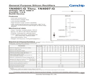
1N4007-G Voltage: 50 to 1000 V Current: 1.0 A RoHS Device DO-41 Features - Low cost construction. - Fast forward voltage drop. - Low reverse leakage. - High forward surge current capability. 1.000(25.40) Min. - High soldering temperature guarantee: 260 OC/10 seconds, 0.375"(9.5mm) lead length at 5lbs(2.3kg) tension. 0.205(5.21) 0.161(4.10) Mechanical data 0.117(2.97) DIA. 0.078(2.00) DIA. - Case: Transfer molded plastic, DO-41 - Epoxy: UL 94V-0 rate flame retardant 1.000(25.40) Min. - Polarity: Indicated by cathode band - Lead: Plated axial lead, solderable per MIL-STD-750, method 2026 0.035(0.90) DIA. 0.027(0.70) DIA. - Mounting position: Any - Weight: 0.012ounce, 0.34 grams(approx.). Dimensions in inches and (millimeter) Electrical Characteristics (at TA=25C unless otherwise noted) Ratings at 25C ambient temperature unless otherwise specified. Single phase, half wave, 60Hz, resistive or inductive load. For capacitive load derate current by 20%. Symbol 1N4001 -G 1N4002 -G 1N4003 -G 1N 4004 -G 1N
 4 Pages, 446 KB, Original
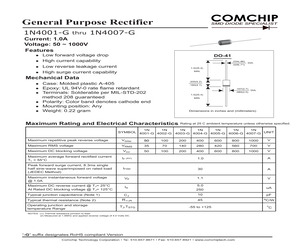
1N4007-G Current: 1.0A Voltage: 50 ~ 1000V Features Low forward voltage drop High current capability Low reverse leakage current High surge current capability DO-41 .034(.86) DIA. .028(.71) 1.0(25.4) MIN. Mechanical Data .205(5.2) Case: Molded plastic A-405 Epoxy: UL 94V-0 rate flame retardant Terminals: Solderable per MIL-STD-202 method 208 guaranteed Polarity: Color band denotes cathode end Mounting position: Any Weight: 0.22 gram .160(4.1) .107(2.7) DIA. .080(2.0) 1.0(25.4) MIN. Dimensions in inches and (millimeters) Maximum Rating and Electrical Characteristics Rating at 25 C ambient temperature unless otherwise specified. 1N 1N 1N 1N 1N 1N 1N SYMBOL 4001-G 4002-G 4003-G 4004-G 4005-G 4006-G 4007-G UNIT Maximum repetitive peak reverse voltage VRRM 50 100 200 400 600 800 1000 V Maximum RMS voltage VRMS 35 70 140 280 420 560 700 V Maximum DC blocking voltage VDC 50 100 200 400 600 800 1000 V Maximum average forward rectified current TL = 55C IF (AV) 1.0 A Peak forward surge current, 8.3ms singl
 2 Pages, 89 KB, Original
1N4007-G Current: 1.0A Voltage: 50 ~ 1000V Features Low forward voltage drop High current capability Low reverse leakage current High surge current capability DO-41 .034(.86) DIA. .028(.71) 1.0(25.4) MIN. Mechanical Data .205(5.2) Case: Molded plastic A-405 Epoxy: UL 94V-0 rate flame retardant Terminals: Solderable per MIL-STD-202 method 208 guaranteed Polarity: Color band denotes cathode end Mounting position: Any Weight: 0.22 gram .160(4.1) .107(2.7) DIA. .080(2.0) 1.0(25.4) MIN. Dimensions in inches and (millimeters) Maximum Rating and Electrical Characteristics Rating at 25 C ambient temperature unless otherwise specified. 1N 1N 1N 1N 1N 1N 1N SYMBOL 4001-G 4002-G 4003-G 4004-G 4005-G 4006-G 4007-G UNIT Maximum repetitive peak reverse voltage VRRM 50 100 200 400 600 800 1000 V Maximum RMS voltage VRMS 35 70 140 280 420 560 700 V Maximum DC blocking voltage VDC 50 100 200 400 600 800 1000 V Maximum average forward rectified current TL = 55C IF (AV) 1.0 A Peak forward surge current, 8.3ms singl
 3 Pages, 99 KB, Original
uF 1A 0.8A 0.2A 1A 470H 220H 47 10k Description X2 400V, 20% 25V, X7R, 20% 25VV, 20% 50V, X7R, 20% 2pin 1000V 600V 600V 250V 0.25A 1.2A 2W, 5% 0.1W, 5% Part Number 890 334 025 017 CS 400BXW12MEFR10X16 TMK107B7105MA-T 860 080 474 010 HMK107B7104MA-T B2P-VH 1N4007-GP RFN1LAM6S TR RRE02VSM6S 39211000000 BM2P129TF DRV060-471 744 747 122 1 ERG-2SJ470 MCR10EZPJ103 3/8 Manufacture Wurth Rubycon Taiyo Yuden Wurth Taiyo Yuden JST Vishay ROHM ROHM Littelfuse ROHM Alphatrans Wurth Panasonic ROHM Configuration mm (inch) 1608 (0603) 1608 (0603) PMDS TUMD2SM SOP8 2012 (0805) No. 60UG070E Rev.001 2018.3 BM2P129TF-EVK-002 User's Guide PCB Size : 25 mm x 45 mm Figure 4. Top Silkscreen (Top view) Figure 5. Bottom Layout (Top view) (c) 2018 ROHM Co., Ltd. 4/8 No. 60UG070E Rev.001 2018.3 BM2P129TF-EVK-002 User's Guide Performance Data -10.8 100 90 VIN=100Vac 80 VIN=100Vac -11.6 VIN=230Vac -12.0 Efficiency [%] Output Voltage [V] -11.2 -12.4 70 VIN=230Vac 60 50 40 30 20 -12.8 10 -13.2 0 0 100 200 300 0 50 Output Curre
 10 Pages, 938 KB, Original