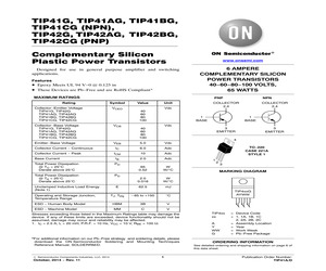
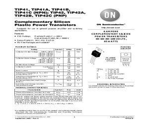
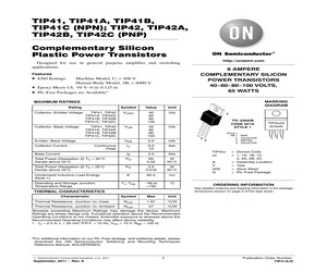
TIP42AG, TIP42BG, TIP42CG(PNP) Complementary Silicon Plastic Power Transistors www.onsemi.com Designed for use in general purpose amplifier and switching applications. Features * Epoxy Meets UL 94 V-0 @ 0.125 in * These Devices are Pb-Free and are RoHS Compliant* 6 AMPERE COMPLEMENTARY SILICON POWER TRANSISTORS 40-60-80-100 VOLTS, 65 WATTS MAXIMUM RATINGS Rating Collector-Emitter Voltage TIP41G, TIP42G TIP41AG, TIP42AG TIP41BG, TIP42BG TIP41CG, TIP42CG Symbol VCEO Value Unit Vdc 40 60 80 100 VCB Emitter-Base Voltage VEB 5.0 Vdc IC 6.0 Adc ICM 10 Adc Base Current IB 2.0 Adc Total Power Dissipation @ TC = 25C Derate above 25C PD 65 0.52 W W/C Total Power Dissipation @ TA = 25C Derate above 25C PD 2.0 0.016 W W/C Unclamped Inductive Load Energy (Note 1) E 62.5 mJ TJ, Tstg - 65 to +150 C ESD - Human Body Model HBM 3B V ESD - Machine Model MM C V Collector Current - Peak Operating and Storage Junction, Temperature Range *For additional information on our Pb-Free strategy and soldering det
 7 Pages, 118 KB, Original
TIP42AG, TIP42BG, TIP42CG(PNP) Complementary Silicon Plastic Power Transistors http://onsemi.com Designed for use in general purpose amplifier and switching applications. Features * Epoxy Meets UL 94 V-0 @ 0.125 in * These Devices are Pb-Free and are RoHS Compliant* 6 AMPERE COMPLEMENTARY SILICON POWER TRANSISTORS 40-60-80-100 VOLTS, 65 WATTS MAXIMUM RATINGS Rating Collector-Emitter Voltage TIP41G, TIP42G TIP41AG, TIP42AG TIP41BG, TIP42BG TIP41CG, TIP42CG Symbol Value Unit VCEO Vdc 40 60 80 100 VCB Emitter-Base Voltage VEB 5.0 Vdc Vdc 3 EMITTER IC 6.0 Adc 10 Adc Base Current IB 2.0 Adc Total Power Dissipation @ TC = 25C Derate above 25C PD 65 0.52 W W/C Total Power Dissipation @ TA = 25C Derate above 25C PD Unclamped Inductive Load Energy (Note 1) E 62.5 mJ TJ, Tstg - 65 to +150 C ESD - Human Body Model HBM 3B V ESD - Machine Model MM C V Stresses exceeding Maximum Ratings may damage the device. Maximum Ratings are stress ratings only. Functional operation above the Recommended Opera
 7 Pages, 138 KB, Original
TIP42AG, TIP42BG, TIP42CG(PNP) Complementary Silicon Plastic Power Transistors www.onsemi.com Designed for use in general purpose amplifier and switching applications. Features * Epoxy Meets UL 94 V-0 @ 0.125 in * These Devices are Pb-Free and are RoHS Compliant* 6 AMPERE COMPLEMENTARY SILICON POWER TRANSISTORS 40-60-80-100 VOLTS, 65 WATTS MAXIMUM RATINGS Rating Collector-Emitter Voltage TIP41G, TIP42G TIP41AG, TIP42AG TIP41BG, TIP42BG TIP41CG, TIP42CG Symbol VCEO Value Unit Vdc 40 60 80 100 VCB Emitter-Base Voltage VEB 5.0 Vdc IC 6.0 Adc ICM 10 Adc Base Current IB 2.0 Adc Total Power Dissipation @ TC = 25C Derate above 25C PD 65 0.52 W W/C Total Power Dissipation @ TA = 25C Derate above 25C PD 2.0 0.016 W W/C Unclamped Inductive Load Energy (Note 1) E 62.5 mJ TJ, Tstg - 65 to +150 C ESD - Human Body Model HBM 3B V ESD - Machine Model MM C V Collector Current - Peak Operating and Storage Junction, Temperature Range *For additional information on our Pb-Free strategy and soldering det
 8 Pages, 129 KB, Original
TIP42AG, TIP42BG, TIP42CG(PNP) Complementary Silicon Plastic Power Transistors www.onsemi.com Designed for use in general purpose amplifier and switching applications. Features * Epoxy Meets UL 94 V-0 @ 0.125 in * These Devices are Pb-Free and are RoHS Compliant* 6 AMPERE COMPLEMENTARY SILICON POWER TRANSISTORS 40-60-80-100 VOLTS, 65 WATTS MAXIMUM RATINGS Rating Collector-Emitter Voltage TIP41G, TIP42G TIP41AG, TIP42AG TIP41BG, TIP42BG TIP41CG, TIP42CG Symbol VCEO Value Unit Vdc 40 60 80 100 VCB Emitter-Base Voltage VEB 5.0 Vdc IC 6.0 Adc ICM 10 Adc Base Current IB 2.0 Adc Total Power Dissipation @ TC = 25C Derate above 25C PD 65 0.52 W W/C Total Power Dissipation @ TA = 25C Derate above 25C PD 2.0 0.016 W W/C Unclamped Inductive Load Energy (Note 1) E 62.5 mJ TJ, Tstg - 65 to +150 C ESD - Human Body Model HBM 3B V ESD - Machine Model MM C V Collector Current - Peak Operating and Storage Junction, Temperature Range *For additional information on our Pb-Free strategy and soldering det
 8 Pages, 272 KB, Original
-220 (Pb-Free) 50 Units / Rail TIP42A TO-220 50 Units / Rail TO-220 (Pb-Free) 50 Units / Rail TO-220 50 Units / Rail TO-220 (Pb-Free) 50 Units / Rail TO-220 50 Units / Rail TO-220 (Pb-Free) 50 Units / Rail TIP41 TIP41AG TIP41B TIP41BG TIP41C TIP41CG TIP42 TIP42AG TIP42B TIP42BG TIP42C TIP42CG http://onsemi.com 2 PD, POWER DISSIPATION (WATTS) TIP41, TIP41A, TIP41B, TIP41C (NPN); TIP42, TIP42A, TIP42B, TIP42C (PNP) TA 4.0 TC 80 3.0 60 2.0 40 1.0 20 0 0 TC TA 0 40 20 60 100 80 T, TEMPERATURE (C) 120 140 160 Figure 1. Power Derating VCC +30 V 2.0 RC 0.7 0.5 SCOPE +11 V -9.0 V tr, tf 10 ns DUTY CYCLE = 1.0% t, TIME (s) RB 0 TJ = 25C VCC = 30 V IC/IB = 10 1.0 25 ms D1 0.3 0.2 tr 0.1 0.07 0.05 -4 V RB and RC VARIED TO OBTAIN DESIRED CURRENT LEVELS 0.03 0.02 0.06 D1 MUST BE FAST RECOVERY TYPE, e.g.: 1N5825 USED ABOVE IB 100 mA MSD6100 USED BELOW IB 100 mA Figure 2. Switching Time Test Circuit td @ VBE(off) 5.0 V 0.1 0.2 0.4 0.6 1.0 2.0 IC, COLLECTOR CURRENT (AMP) Figure 3. Turn-On Time http://onsemi.com
 6 Pages, 91 KB, Original
41C TIP41CG TIP42 TO-220 50 Units / Rail TIP42G TO-220 (Pb-Free) 50 Units / Rail TIP42A TO-220 50 Units / Rail TO-220 (Pb-Free) 50 Units / Rail TO-220 50 Units / Rail TO-220 (Pb-Free) 50 Units / Rail TO-220 50 Units / Rail TO-220 (Pb-Free) 50 Units / Rail TIP42AG TIP42B TIP42BG TIP42C TIP42CG http://onsemi.com 2 PD, POWER DISSIPATION (WATTS) TIP41, TIP41A, TIP41B, TIP41C (NPN); TIP42, TIP42A, TIP42B, TIP42C (PNP) TA 4.0 TC 80 3.0 60 2.0 40 1.0 20 0 0 TC TA 0 40 20 60 100 80 T, TEMPERATURE (C) 120 140 160 Figure 1. Power Derating VCC +30 V 2.0 RC 0.7 0.5 SCOPE +11 V -9.0 V tr, tf 10 ns DUTY CYCLE = 1.0% t, TIME (s) RB 0 TJ = 25C VCC = 30 V IC/IB = 10 1.0 25 ms D1 0.3 0.2 tr 0.1 0.07 0.05 -4 V RB and RC VARIED TO OBTAIN DESIRED CURRENT LEVELS 0.03 0.02 0.06 D1 MUST BE FAST RECOVERY TYPE, e.g.: 1N5825 USED ABOVE IB 100 mA MSD6100 USED BELOW IB 100 mA Figure 2. Switching Time Test Circuit td @ VBE(off) 5.0 V 0.1 0.2 0.4 0.6 1.0 2.0 IC, COLLECTOR CURRENT (AMP) Figure 3. Turn-On Time http://onsemi.com
 6 Pages, 72 KB, Original
42G TO-220 (Pb-Free) 50 Units / Rail TIP42A TO-220 50 Units / Rail TO-220 (Pb-Free) 50 Units / Rail TO-220 50 Units / Rail TO-220 (Pb-Free) 50 Units / Rail TO-220 50 Units / Rail TO-220 (Pb-Free) 50 Units / Rail TIP41AG TIP41B TIP41BG TIP41C TIP41CG TIP42 TIP42AG TIP42B TIP42BG TIP42C TIP42CG http://onsemi.com 3 PD, POWER DISSIPATION (WATTS) TIP41, TIP41A, TIP41B, TIP41C (NPN); TIP42, TIP42A, TIP42B, TIP42C (PNP) TA 4.0 TC 80 3.0 60 2.0 40 1.0 20 0 0 TC TA 20 0 40 120 60 100 80 T, TEMPERATURE (C) 140 160 Figure 2. Power Derating VCC +30 V 2.0 RC 0.7 0.5 SCOPE +11 V -9.0 V tr, tf 10 ns DUTY CYCLE = 1.0% t, TIME (s) RB 0 TJ = 25C VCC = 30 V IC/IB = 10 1.0 25 ms D1 0.3 0.2 tr 0.1 0.07 0.05 -4 V RB and RC VARIED TO OBTAIN DESIRED CURRENT LEVELS 0.03 0.02 0.06 D1 MUST BE FAST RECOVERY TYPE, e.g.: 1N5825 USED ABOVE IB 100 mA MSD6100 USED BELOW IB 100 mA td @ VBE(off) 5.0 V 0.1 1.0 0.2 2.0 0.4 0.6 IC, COLLECTOR CURRENT (AMP) Figure 4. Turn-On Time Figure 3. Switching Time Test Circuit http://onsemi.com
 7 Pages, 118 KB, Original
41C TIP41CG TIP42 TO-220 50 Units / Rail TIP42G TO-220 (Pb-Free) 50 Units / Rail TIP42A TO-220 50 Units / Rail TO-220 (Pb-Free) 50 Units / Rail TO-220 50 Units / Rail TO-220 (Pb-Free) 50 Units / Rail TO-220 50 Units / Rail TO-220 (Pb-Free) 50 Units / Rail TIP42AG TIP42B TIP42BG TIP42C TIP42CG http://onsemi.com 2 PD, POWER DISSIPATION (WATTS) TIP41, TIP41A, TIP41B, TIP41C (NPN); TIP42, TIP42A, TIP42B, TIP42C (PNP) TA 4.0 TC 80 3.0 60 2.0 40 1.0 20 0 0 TC TA 20 0 40 120 60 100 80 T, TEMPERATURE (C) 140 160 Figure 1. Power Derating VCC +30 V 2.0 RC 0.7 0.5 SCOPE +11 V -9.0 V tr, tf 10 ns DUTY CYCLE = 1.0% t, TIME (s) RB 0 TJ = 25C VCC = 30 V IC/IB = 10 1.0 25 ms D1 0.3 0.2 tr 0.1 0.07 0.05 -4 V RB and RC VARIED TO OBTAIN DESIRED CURRENT LEVELS 0.03 0.02 0.06 D1 MUST BE FAST RECOVERY TYPE, e.g.: 1N5825 USED ABOVE IB 100 mA MSD6100 USED BELOW IB 100 mA td @ VBE(off) 5.0 V 0.1 1.0 0.2 2.0 0.4 0.6 IC, COLLECTOR CURRENT (AMP) Figure 3. Turn-On Time Figure 2. Switching Time Test Circuit http://onsemi.com
 6 Pages, 112 KB, Original
-220 (Pb-Free) 50 Units / Rail TIP42A TO-220 50 Units / Rail TO-220 (Pb-Free) 50 Units / Rail TO-220 50 Units / Rail TO-220 (Pb-Free) 50 Units / Rail TO-220 50 Units / Rail TO-220 (Pb-Free) 50 Units / Rail TIP41 TIP41AG TIP41B TIP41BG TIP41C TIP41CG TIP42 TIP42AG TIP42B TIP42BG TIP42C TIP42CG 2 TIP41, TIP41A, TIP41B, TIP41C (NPN); TIP42, TIP42A, TIP42B, TIP42C (PNP) PACKAGE DIMENSIONS TO-220 CASE 221A-09 ISSUE AE -TC F B T S 4 DIM A B C D F G H J K L N Q R S T U V Z A Q 1 2 3 U H K Z L R V SEATING PLANE NOTES: 1. DIMENSIONING AND TOLERANCING PER ANSI Y14.5M, 1982. 2. CONTROLLING DIMENSION: INCH. 3. DIMENSION Z DEFINES A ZONE WHERE ALL BODY AND LEAD IRREGULARITIES ARE ALLOWED. J G D N 6 INCHES MIN MAX 0.570 0.620 0.380 0.405 0.160 0.190 0.025 0.035 0.142 0.161 0.095 0.105 0.110 0.155 0.014 0.025 0.500 0.562 0.045 0.060 0.190 0.210 0.100 0.120 0.080 0.110 0.045 0.055 0.235 0.255 0.000 0.050 0.045 ----0.080 MILLIMETERS MIN MAX 14.48 15.75 9.66 10.28 4.07 4.82 0.64 0.88 3.61 4.09 2.42 2.66 2.80 3.93
 3 Pages, 65 KB, Original