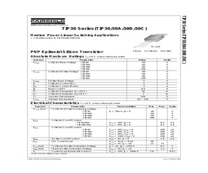
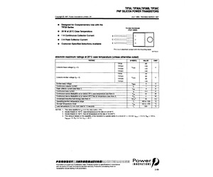
TIP30B/TIP30C PNP Epitaxial Silicon Transistor Features * Complementary to TIP29/TIP29A/TIP29B/TIP29C 1. Base 2. Collector 3. Emitter Absolute Maximum Ratings TC=25C unless otherwise noted Symbol Parameter Value Units VCBO Collector-Base Voltage : TIP30 : TIP30A : TIP30B : TIP30C - 40 - 60 - 80 - 100 V V V V VCEO Collector-Emitter Voltage : TIP30 : TIP30A : TIP30B : TIP30C - 40 - 60 - 80 - 100 V V V V VEBO Emitter-Base Voltage -5 V IC Collector Current (DC) -1 A ICP Collector Current (Pulse) -3 A IB Base Current - 0.4 A PC Collector Dissipation (TC=25C) 30 W Collector Dissipation (Ta=25C) 2 W TJ Junction Temperature 150 C TSTG Storage Temperature - 65 ~ 150 C (c) 2008 Fairchild Semiconductor Corporation TIP30/TIP30A/TIP30B/TIP30C Rev. A www.fairchildsemi.com 1 TIP30/TIP30A/TIP30B/TIP30C -- PNP Epitaxial Silicon Transistor July 2008 Symbol VCEO(sus) ICEO ICES Parameter * Collector-Emitter Sustaining Voltage : TIP30 : TIP30A : TIP30B
 5 Pages, 479 KB, Original
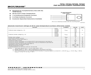
TIP30B, TIP30C PNP SILICON POWER TRANSISTORS Copyright (c) 1997, Power Innovations Limited, UK JULY 1968 - REVISED MARCH 1997 Designed for Complementary Use with the TIP29 Series TO-220 PACKAGE (TOP VIEW) 30 W at 25C Case Temperature 1 A Continuous Collector Current B 1 3 A Peak Collector Current C 2 Customer-Specified Selections Available E 3 Pin 2 is in electrical contact with the mounting base. MDTRACA absolute maximum ratings at 25C case temperature (unless otherwise noted) RATING SYMBOL TIP30 Collector-base voltage (IE = 0) Collector-emitter voltage (IB = 0) TIP30A TIP30B VCBO -100 -140 -40 TIP30B VCEO TIP30C Continuous collector current Peak collector current (see Note 1) Continuous base current Continuous device dissipation at (or below) 25C case temperature (see Note 2) Continuous device dissipation at (or below) 25C free air temperature (see Note 3) Unclamped inductive load energy (see Note 4) Operating junction temperature range Storage temperature range Lead t
 6 Pages, 132 KB, Original
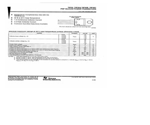
TIP30B, TIP30C PNP SILICON POWER TRANSISTORS Copyright 1997, Power Innovations Limited, UK JULY 1968 - REVISED MARCH 1997 @ Designed for Complementary Use with the TIP29 Series TO-220 PACKAGE (TOP VIEW) 30 W at 25C Case Temperature 1 A Continuous Collector Current 3 A Peak Collector Current Cc C) Customer-Specified Selections Available Pin 2 is in electrical contact with the mounting base. MDTRACA absolute maximum ratings at 25C case temperature (unless otherwise noted) RATING SYMBOL VALUE UNIT TIP30 -80 TIP30A -100 Collector-base voltage (Ip = 0) TIP30B Veso 420 Vv TIP30C -140 TIP30 -40 . TIP30A -60 Collector-emitter voltage (lg = 0) TIP30B VcEo 80 Vv TIP30C -100 Emitter-base voltage VeBo -5 Vv Continuous collector current lo -1 A Peak collector current (see Note 1) lom 3 A Continuous base current lp -0.4 A Continuous device dissipation at (or below) 25C case temperature (see Note 2) Prot 30 Ww Continuous device dissipation at (or below) 25C free air temperature (see No
 6 Pages, 214 KB, Scan
TIP30B, TIP30C PNP SILICON POWER TRANSISTORS Designed for Complementary Use with the TIP29 Series TO-220 PACKAGE (TOP VIEW) 30 W at 25C Case Temperature 1 A Continuous Collector Current 3 A Peak Collector Current B 1 C 2 Customer-Specified Selections Available E 3 This series is currently available, but not recommended for new designs. Pin 2 is in electrical contact with the mounting base. MDTRACA absolute maximum ratings at 25C case temperature (unless otherwise noted) RATING SYMBOL TIP30 Collector-base voltage (IE = 0) TIP30A TIP30B V CBO Emitter-base voltage Continuous collector current TIP30B TIP30C VCEO VEBO IC ICM Continuous device dissipation at (or below) 25C case temperature (see Note 2) Ptot Continuous device dissipation at (or below) 25C free air temperature (see Note 3) Unclamped inductive load energy (see Note 4) Operating junction temperature range Storage temperature range Lead temperature 3.2 mm from case for 10 seconds NOTES: 1. 2. 3. 4. V -120 -40 Peak
 4 Pages, 136 KB, Original
TIP30B, TIP30C PNP SILICON POWER TRANSISTORS Designed for Complementary Use with the TIP29 Series 30 W at 25C Case Temperature 1 A Continuous Collector Current B 1 3 A Peak Collector Current C 2 Customer-Specified Selections Available E 3 TO-220 PACKAGE (TOP VIEW) Pin 2 is in electrical contact with the mounting base. MDTRACA absolute maximum ratings at 25C case temperature (unless otherwise noted) RATING Collector-base voltage (IE = 0) SYMBOL TIP30 -80 TIP30A -100 TIP30B V CBO -140 TIP30 -40 TIP30B VCEO UNIT V -120 TIP30C TIP30A Collector-emitter voltage (IB = 0) VALUE -60 V -80 -100 TIP30C VEBO -5 V IC -1 A ICM -3 A IB -0.4 A Continuous device dissipation at (or below) 25C case temperature (see Note 2) Ptot 30 W Continuous device dissipation at (or below) 25C free air temperature (see Note 3) Ptot 2 W 1/2LIC2 32 mJ C Emitter-base voltage Continuous collector current Peak collector current (see Note 1) Continuous base current Unclamped inductive load energy (see Note 4)
 4 Pages, 60 KB, Original
TIP30B, TIP30C PNP SILICON POWER TRANSISTORS Copyright (c) 1997, Power Innovations Limited, UK JULY 1968 - REVISED MARCH 1997 Designed for Complementary Use with the TIP29 Series TO-220 PACKAGE (TOP VIEW) 30 W at 25C Case Temperature 1 A Continuous Collector Current B 1 3 A Peak Collector Current C 2 Customer-Specified Selections Available E 3 Pin 2 is in electrical contact with the mounting base. MDTRACA absolute maximum ratings at 25C case temperature (unless otherwise noted) RATING SYMBOL TIP30 Collector-base voltage (IE = 0) TIP30A TIP30B VCBO TIP30C Collector-emitter voltage (IB = 0) TIP30B Continuous collector current Peak collector current (see Note 1) Continuous base current Continuous device dissipation at (or below) 25C case temperature (see Note 2) Continuous device dissipation at (or below) 25C free air temperature (see Note 3) Unclamped inductive load energy (see Note 4) Operating junction temperature range Storage temperature range Lead temperature 3.2 mm f
 6 Pages, 60 KB, Original
inear Switching Applications * Complementary to TIP29/29A/29B/29C TO-220 1 1.Base PNP Epitaxial Silicon Transistor 2.Collector 3.Emitter Absolute Maximum Ratings TC=25C unless otherwise noted Symbol VCBO Collector-Base Voltage Parameter : TIP30 : TIP30A : TIP30B : TIP30C Value - 40 - 60 - 80 - 100 Units V V V V - 40 - 60 - 80 - 100 V V V V VCEO Collector-Emitter Voltage : TIP30 : TIP30A : TIP30B : TIP30C VEBO Emitter-Base Voltage -5 V IC Collector Current (DC) -1 A ICP Collector Current (Pulse) -3 A IB Base Current - 0.4 A W PC Collector Dissipation (TC=25C) 30 PC Collector Dissipation (Ta=25C) 2 W TJ Junction Temperature 150 C TSTG Storage Temperature - 65 ~ 150 C Electrical Characteristics TC=25C unless otherwise noted Symbol VCEO(sus) ICEO ICES Parameter * Collector-Emitter Sustaining Voltage : TIP30 : TIP30A : TIP30B : TIP30C Collector Cut-off Current : TIP30/30A : TIP30B/30C Test Condition IC = -30mA, IB = 0 Min. Max. -40 -60 -80 -100 Units V V V V VCE
 8 Pages, 144 KB, Original
TIP30B, TIP30C PNP SILICON POWER TRANSISTORS Designed for Complementary Use with the TIP29 Series 30 W at 25C Case Temperature 1 A Continuous Collector Current B 1 3 A Peak Collector Current C 2 Customer-Specified Selections Available E 3 TO-220 PACKAGE (TOP VIEW) Pin 2 is in electrical contact with the mounting base. MDTRACA absolute maximum ratings at 25C case temperature (unless otherwise noted) RATING Collector-base voltage (IE = 0) Collector-emitter voltage (IB = 0) SYMBOL VALUE TIP30 -80 TIP30A -100 TIP30B V CBO -140 TIP30 -40 TIP30B VCEO V -120 TIP30C TIP30A UNIT -60 V -80 -100 TIP30C VEBO -5 V IC -1 A ICM -3 A IB -0.4 A Continuous device dissipation at (or below) 25C case temperature (see Note 2) Ptot 30 W Continuous device dissipation at (or below) 25C free air temperature (see Note 3) Ptot 2 W 1/2LIC2 32 mJ C Emitter-base voltage Continuous collector current Peak collector current (see Note 1) Continuous base current Unclamped inductive load energy (see Note 4)
 5 Pages, 81 KB, Original
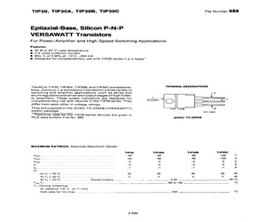
TIP30B, TIP30C File Number 988 Epitaxial-Base, Silicon P-N-P VERSAWATT Transistors For Power-Amplifier and High-Speed-Switching Applications Features: m 30 W at 25C case temperature 8 3A rated collector current @ Min. fr Of 3 MHz at -10 V, -200 mA @ Designed for complementary use with TIP29-series n-p-n types* The RCA-TIP30, TIP30A, TIP30B, and TIP30C are epitaxial- TERMINAL DESIGNATIONS base, silicon p-n-p transistors intended fora wide variety of switching and amplifier applications, such as series and E shunt regulators and driver and output stages of high-fideli- tu ty amplifiers. These power transistors are designed for Cc _ Cc complementary use with devices in the TIP29 series. They (FLANGE) C) Pe differ from each other in voltage ratings. They are supplied in the JEDEC TO-220AB (VERSAWATT) TOP VIEW c plastic package. 92CS-39969 * Technical data for the TiP29-series devices are given in RCA data bulletin File No. 990 JEDEC TO-220AB MAXIMUM RATINGS, Absolute-Maximum Values: TIP3
 4 Pages, 109 KB, Scan
TIP30B, TIP30C PNP SILICON POWER TRANSISTORS Copyright 1997, Power innovations Limited, UK JULY: 1968 - REVISED MARCH 1997 ee -_ @ Designed for Complementary Use with the TIP29 Series TO-220 PACKAGE @ 30 W at 25C Case Temperature {TOP VIEW) @ 1A Continuous Collector Current @ 3A Peak Collector Current c C) @ Customer-Specified Selections Available Pin 2 is in electrical contact with the mounting base. MDTRACA absolute maximum ratings at 25C case temperature (unless otherwise noted) RATING SYMBOL VALUE UNIT TIP3OA -100 Collector-base voltage (lp = 0) TIP90B Veso TIP30C TIP30A TIP30B TIP30C Collactor-emitter voltage (Ig = 0) range mm case NOTES: 1. This value applies for{, $0.3 ms, duty cycle < 10%. 2, Derate ineasty to 150C case temperature. at the rate of 0.24 W/C. 3. Derate finearly to 150C free air temperature at fhe rate of 16 MWAC. 4. This rating is based on the capability of the transistor to operate safely in a circuit of: L = 20 MH. gion) = -0-4 A, Age = 100 Q, Vee(ony = 0, Rg
 4 Pages, 172 KB, Scan
TIP30B, TIP30C P-N-P SINGLE-DIFFUSED MESA SILICON POWER TRANSISTORS FOR POWER-AMPLIFIER AND HIGH-SPEED-SWITCHING APPLICATIONS DESIGNED FOR COMPLEMENTARY USE WITH TIP29, TIP29A, TIP29B, TIP29C 30 W at 25C Case Temperature e 1A Rated Colfector Current e Min fy of 3 MHz at 10 V, 200 mA mechanical data THE COLLECTOR IS IN ELECTRICAL CONTACT WITH THE MOUNTING TAB MECHANICAL INTERCHANGEABILITY OF T1P39 PLASTIC PACKAGE WITH 10-66 QUTLINE (10.66 DIMENSIONS! 1 oo THIS PORTION OF LEADS, 5e05 FREE OF FLASH | } COLLECTOR . OL, tee EMITTER *= o.390 a 0210 ati 1 Fog on o.1 0.018 3 Leaps 37% 0190 fa ba. - oF 0.055. ous os 00% 0210 6.035 CASE TEMPERATURE 0.030 MIN i2 PLACES) Rad 2 PLACES? ALL DIMENSIONS ARE IN INCHES MEASUREMENT POINT DOEdIL BOEdIL VOEdIL OFdI.L SAdAL S96L ANP '9S60189 S10 ON NILA11NG S30V 1d3y OZ6L H3EW3I3 LOVLLOZ S-10 ON NILSTING a NOTES: Collector-Base Voltage Collector-Emitter Voltage (See Note 1) Emitter-Base Voltage . Continuous Coflector Current Peak Collector Current (See Note 2) Continu
 4 Pages, 122 KB, Scan
16 TIP29D MJE15030 3-972 TIP511 MJ15011 3716 TIP29E MJE15030 3-972 TIP512 MJ15011 3-716 TIP29F MJE15030 3-972 TIP513 MJ15012 3-716 TIP30 TIP30 3-1071 TIP514 MJE15030 3-972 TIP3055 TIP3055 3-1108 TIPS17 2N6339 3-188 TIP30A TIP30A 3-1071 TIPS18 2N6341 3-188 TIP30B TIP30B 31071 TIP519 MJ15012 3-716 TIP30C TIP30C 3-1071 TIP520 MJ15012 3-716 TIP30D MJE15031 3-972 TIPS21 2N6211 3-161 TIP30E MJE15031 3-972 TIP522 2N6211 3-161 TIP30F MJE15031 3-972 TIP523 MJ15012 3-716 TIP31 TIP31 3-1073 TIP524 2N5497 3211 TIP31A TIP31A 3-1073 TIP525 MJ15011 3-716 TIP31B TIP31B 3-1073 TIP526 MJ15011 3-716 TIP31C TIP31C 3-1073 TIP527 MJ15012 3-716 TIP31D MJE15030 3-972 TIP528 MJ15012 3-716 TIP31E MJE15030 3-972 TIP536 MJ16006 3-742 TIP31F MJE15030 3-972 TIP545 MJ15016 39 TIP32 TIP32 3-1073 TIP546 MJ15016 3-9 TIP32A TIP32A 3-1073 TIP550 MJ12002 3-637 TIP32B TIP32B 3-1073 TIP5S1 MJ12003 3-642 TIP32C TIP32C 3-1073 TIP552 MJ12004 3-644 TIP32D MJE15031 3-972 TIP553 MJ12004 3-644 TIP32E MJE15031 3-972 TIPS54 MJ1308
 4 Pages, 161 KB, Scan
TIP30B, TIP30C PNP SILICON POWER TRANSISTORS JULY 1968 - REVISED MAY 1995 aS @ Designed for Complementary Use with the TIP29 Series TO-220 PACKAGE OP VIEW! 30 W at 25C Case Temperature ) 1 A Continuous Collector Current B 1 3 3 A Peak Collector Current eo Pin 2 is in electrical contact with the mounting base. MOTRAC Customer-Specified Selections Available E absolute maximum ratings at 25C case temperature (unless otherwise noted) RATING SYMBOL VALUE UNIT TIP30A v TIP30B ceo TIP30C Collector-base voitage (I = 0) TIP30A TIP30B TIP30G Coltector-amitter voltage (Ip = 0) energy range range mm case NOTES: 1. This value applies for t, $0.3 ms, duty cycle < 10%. 2. Derate linearly to 150C case temperature at the rate of 0.24 WC. 3. Derate linearly to 150C free air temperature at the rate of 16 mW/C. 4. This rating is based on the capability of the transistor to operate safely in a circuit of: L = 20 mH, lajon) = -0.4 A, Reg = 100 9, Vegi = 0, Rg = 0.1 0, Veg = -20 V. : PRODUCTIO
 8 Pages, 276 KB, Scan
922 2SA939 2SA963 2SA966 2SA980 2SA1008 2SA1010 2SA1012 2SA1020 2SA1045 2SA1046 2SA1063 2SA1069 2SA1110 2SA1307 , ,,, MJE170 BD238 BD240B BD240A BDW52C TIP2955 TIP2955 BD242A BD242B 2N6109 2N6107 TIP30C BD438 BD440 BD442 MJE350 2N3789 2N3790 TIP32C TIP30C TIP30B MJE350 MJE350 BDW52C TIP32C 2N5876 BD438 BD438 BD242B MJE350 MJE350 MJE210 TIP2955 2N4918 MJE350 MJE171 TIP32 BDW52B TIP32C TIP42C TIP42A TIP32 2N6052 2N6052 TIP2955 TIP42B MJE350 TIP42B MJE172 BD238 BD240B BD240B BDW52C TIP2955 TIP2955 BD242A BD242B 2N6109 2N6107 TIP30C BD438 BD440 BD442 MJE350 2N3790 2N3790 TIP32C TIP30C TIP30B MJE350 MJE350 BDW52C TIP32C BDW52C BD438 BD438 BD242B MJE350 MJE350 MJE210 TIP2955 2N4918 MJE350 MJE172 TIP32A BDW52C TIP32C TIP42C TIP42A TIP32A 2N6052 2N6052 TIP2955 TIP42B MJE350 TIP42B * Product in Development please contact your nearest Sales Office 12 SGS-THOMSON SGS-THOMSON NEAREST PREFERRED 2SA1326 2SA1329 2SA1357 2SAB77 2SB1020 2SB1024 2SB434 2SB435 2SB506 2SB507 2SB509 2SB511 2SB513 2SB514
 38 Pages, 229 KB, Original
TIP30B, TIP30C, . TIP30D, TIP3OE, TIP3OF 1283 P-N-P SILICON POWER TRANSISTORS JULY 1968 REVISED OCTOBER 1984 Designed for Complementary Use With TIP29 series 30 W at 25C Case Temperature 1 A Continuous Collector Current 3 A Peak Collector Current Minimum ft of 3 MHz at 10 V,0.2A Customer Specified Selections Available Designed for Power Amplifier and High-Speed Switching Applications : device schematic TO-220AB PACKAGE FT ee eee EMITTER COLLECTOR BASE THE COLLECTOR IS IN ELECTRICAL CONTACT WITH THE MOUNTING TAB absolute maximum ratings at 25C case temperature (unless otherwise noted) TIP30O TIP30A TIP30B TIP30C current current (see current area at case temperature at case temperature {see Note 2) at temperature (see Note 3) energy collector storage temperature range mm case 1 a 2 > o Oo a - NOTES: 1. This value applies for ty, < 0.3 ms, duty cycle < 10%. 2. Derate linearly to 150C case temperature at the rate of 0.24 W/C. 3. Derate linearly to 150C free-air temperature at the rate of
 7 Pages, 400 KB, Scan