14 R:3.30V T:3.30V 4.7k R608 C632 DC SW /BINT SYMTIM_IN 470 Q601 LTC023JEBFS8 /IF_CS CN719 0.1u VDDQ 14 RREF 13 GNDQ 16 IoUTC 15 C644 390 270n (D) (-92) 0.01u R:5.01V T:5.01V 50R L613 R:3.30V T:3.30V 2 RIPPLE FILTER 100p 50R 22p R607 470 C637 1u C634 D601 SMV1705-079LF 0.1u C627 GNDC 18 VDDC 17 40 VDDL C624 41 CXVM C625 0.1u 1000p 42 LoN C628 0.01u 43 LoP C630 0.1u 44 CXVL 45 GNDI C631 46 CXIF 0.1u 47 IFIN C636 48 VDDI 0.1u C635 R603 L604 IF_DI 3p (B) C869 4 C347 0 L855 C873 22p B10 C10 C8 D8 D9 D10 E7 E8 H10 E9 E10 F9 F10 G9 G10 E6 F6 G6 F8 F7 G7 G8 H7 H8 H9 J8 J10 R335 50R_700 L607 Q602 LSCR523EBFS8 R410 R404 4.7k (D) DC SW 10n C866 L852 22p 2nd_VCO C616 33p (G) C621 /UDET PLL_MOD 0.01u C623 33p (G) D600 VCO FREQUENCY CONTROL CTS1 C617 BCLK 330 12p (G) 3p (B) 270n L603 BCLK0 R849 10u MCH3914-H/8/ Q600 C611 WCLK C608 SMV1705-079LF D600 VCO OSCILLATION RTS1 L600 R604 C622 22 1.80V R406 LNA_EN L608 0.01u DISP_VER USB_SW Q600 C620 R:3.30V T:3.30V L605 RTS2 0.012u 680 C614 C612 R739 1k
 94 Pages, 6783 KB, Original
er VCON2 VCON1 VCOP1 VCOP2 VCO Output Buffer Amplifier L1 should have a Q>30 L1 C1 C2 C3 CV2 CV1 R1 R2 Input from Loop Filter Figure 6 Example External Components - VCO External Tank Circuit L1 C1 C2 C3 51nH (Note 1) 8.2pF (Note 2) 27pF 27pF CV1 CV2 R1 R2 SMV1705-079LF SMV1705-079LF 10k 10k Note 1: Tolerance of 2% or better recommended Note 2: Tolerance of 5% or better recommended Table 5 Internal VCO Amplifier Tank Circuit for 180MHz Operation 2012 CML Microsystems Plc 10 D/973/8 Quadrature Modulator/Demodulator CMX973 Alternative diodes may be used for CV1,CV2, for example the Toshiba 1S305FCT (for which no other value changes should be necessary). For increased tuning range the Skyworks SMV1249-079LF can be used: in this case changing the tank circuit values is recommended. For operation at 180MHz, make L1 = 56nH and C1=6.8pF, then C2 and C3 can be adjusted to give the desired tuning range: with C2, C3 = 27pF the VCO gain (Kv) = 15 MHz/V and with C2, C3 = 12pF, Kv = 8MHz/V. For C2
 47 Pages, 1067 KB, Original
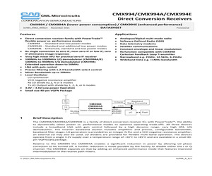
CON2 VCON1 VCOP2 VCOP1 VCO Output Buffer Amplifier L1 should have a Q>30 L1 C1 C2 C3 CV2 CV1 R1 R2 Input from Loop Filter Figure 10 Example External Components - VCO External Tank Circuit L1 C1 C2 C3 8.2 nH (Note 1) 8.2 pF (Note 2) 22pF 22pF CV1 CV2 R1 R2 SMV1705-079LF SMV1705-079LF 10k 10k Note 1: Tolerance of 2% or better recommended Note 2: Tolerance of 5% or better recommended Table 11 Internal VCO Amplifier Tank Circuit for 440MHz Operation 2013 CML Microsystems Plc 16 D/994/14 Direct Conversion Receiver CMX994 Output to Tank Cct DO R2 C1 R1 C3 C2 Figure 11 Example External Components - PLL Loop Filter C1 C2 C3 150nF 1000nF 15nF R1 R2 1.5k 2.4k rd Table 12 3 Order Loop Filter Circuit Values 4.4 RESETN The RESETN pin generates a reset signal when low. The RESETN pin has an internal pull-up resistor of 100k connected to VDDIO. 2013 CML Microsystems Plc 17 D/994/14 Direct Conversion Receiver 5 CMX994 General Description The architecture of the CMX994 integrated circuit and related
 57 Pages, 1135 KB, Original
CON2 VCON1 VCOP2 VCOP1 VCO Output Buffer Amplifier L1 should have a Q>30 L1 C1 C2 C3 CV2 CV1 R1 R2 Input from Loop Filter Figure 10 Example External Components - VCO External Tank Circuit L1 C1 C2 C3 8.2 nH (Note 1) 8.2 pF (Note 2) 22pF 22pF CV1 CV2 R1 R2 SMV1705-079LF SMV1705-079LF 10k 10k Note 1: Tolerance of 2% or better recommended Note 2: Tolerance of 5% or better recommended Table 11 Internal VCO Amplifier Tank Circuit for 440MHz Operation 2013 CML Microsystems Plc 17 D/994/14 Direct Conversion Receiver CMX994 Output to Tank Cct DO R2 C1 R1 C3 C2 Figure 11 Example External Components - PLL Loop Filter C1 C2 C3 150nF 1000nF 15nF R1 R2 1.5k 2.4k rd Table 12 3 Order Loop Filter Circuit Values 4.4 RESETN The RESETN pin generates a reset signal when low. The RESETN pin has an internal pull-up resistor of 100k connected to VDDIO. 2013 CML Microsystems Plc 18 D/994/14 Direct Conversion Receiver 5 CMX994 General Description The architecture of the CMX994 integrated circuit and related
 58 Pages, 1033 KB, Original
er VCON2 VCON1 VCOP1 VCOP2 VCO Output Buffer Amplifier L1 should have a Q>30 L1 C1 C2 C3 CV2 CV1 R1 R2 Input from Loop Filter Figure 6 Example External Components - VCO External Tank Circuit L1 C1 C2 C3 51nH (Note 1) 8.2pF (Note 2) 27pF 27pF CV1 CV2 R1 R2 SMV1705-079LF SMV1705-079LF 10k 10k Note 1: Tolerance of 2% or better recommended Note 2: Tolerance of 5% or better recommended Table 5 Internal VCO Amplifier Tank Circuit for 180MHz Operation 2013 CML Microsystems Plc 10 D/973/10 Quadrature Modulator/Demodulator CMX973 Alternative diodes may be used for CV1,CV2, for example the Toshiba 1S305FCT (for which no other value changes should be necessary). For increased tuning range the Skyworks SMV1249-079LF can be used: in this case changing the tank circuit values is recommended. For operation at 180MHz, make L1 = 56nH and C1=6.8pF, then C2 and C3 can be adjusted to give the desired tuning range: with C2, C3 = 27pF the VCO gain (Kv) = 15 MHz/V and with C2, C3 = 12pF, Kv = 8MHz/V. For C
 49 Pages, 1194 KB, Original
CON2 VCON1 VCOP2 VCOP1 VCO Output Buffer Amplifier L1 should have a Q>30 L1 C1 C2 C3 CV2 CV1 R1 R2 Input from Loop Filter Figure 10 Example External Components - VCO External Tank Circuit L1 C1 C2 C3 8.2 nH (Note 1) 8.2 pF (Note 2) 22pF 22pF CV1 CV2 R1 R2 SMV1705-079LF SMV1705-079LF 10k 10k Note 1: Tolerance of 2% or better recommended Note 2: Tolerance of 5% or better recommended Table 11 Internal VCO Amplifier Tank Circuit for 440MHz Operation 2012 CML Microsystems Plc 15 D/994/13 Direct Conversion Receiver CMX994 Output to Tank Cct DO R2 C1 R1 C3 C2 Figure 11 Example External Components - PLL Loop Filter C1 C2 C3 150nF 1000nF 15nF R1 R2 1.5k 2.4k rd Table 12 3 Order Loop Filter Circuit Values 4.4 RESETN The RESETN pin generates a reset signal when low. The RESETN pin has an internal pull-up resistor of 100k connected to VDDIO. 2012 CML Microsystems Plc 16 D/994/13 Direct Conversion Receiver 5 CMX994 General Description The architecture of the CMX994 integrated circuit and related
 54 Pages, 1126 KB, Original
5-12.5 - 2.3 - 0.5 Max. @ 1 V - 17.3-19.3 Reverse leakage 20 nA max. @ VR = 8 V. Common Cathode SOT-23 Common Cathode SC-70 Single SC-79(1) SMV1263-074LF Marking: EN3 SMV1263-079LF Marking: Cathode SMV1269-074LF Marking: EE3 SMV1270-079LF Marking: Cathode SMV1705-079LF Marking: Cathode SMV1705-004LF Marking: HY3 SMV1705-074LF Marking: HY3 SMV1763-079LF Marking: Cathode SMV1770-079LF Marking: Cathode SMV1771-079LF Marking: Cathode 1. A lower profile (< 0.65 mm) SC-79 package is available; please contact sales. Innovation to GoTM Select products (indicated in blue/bold) are now available for purchase online. The (Pb)-free symbol or "LF" in the part number denotes lead (Pb)-free, RoHS-compliant package. Skyworks Solutions, Inc. * Phone [781] 376-3000 * Fax [781] 376-3100 * sales@skyworksinc.com * www.skyworksinc.com Skyworks Proprietary Information. * Products and product information are subject to change without notice. * Spring 2007 51 Linear Products Varactor Diodes Typical Performance Characteri
 116 Pages, 9103 KB, Original
er VCON2 VCON1 VCOP1 VCOP2 VCO Output Buffer Amplifier L1 should have a Q>30 L1 C1 C2 C3 CV2 CV1 R1 R2 Input from Loop Filter Figure 6 Example External Components - VCO External Tank Circuit L1 C1 C2 C3 51nH (Note 1) 8.2pF (Note 2) 27pF 27pF CV1 CV2 R1 R2 SMV1705-079LF SMV1705-079LF 10k 10k Note 1: Tolerance of 2% or better recommended Note 2: Tolerance of 5% or better recommended Table 5 Internal VCO Amplifier Tank Circuit for 180MHz Operation 2012 CML Microsystems Plc 10 D/973/7 Quadrature Modulator/Demodulator CMX973 Alternative diodes may be used for CV1,CV2, for example the Toshiba 1S305FCT (for which no other value changes should be necessary). For increased tuning range the Skyworks SMV1249-079LF can be used: in this case changing the tank circuit values is recommended. For operation at 180MHz, make L1 = 56nH and C1=6.8pF, then C2 and C3 can be adjusted to give the desired tuning range: with C2, C3 = 27pF the VCO gain (Kv) = 15 MHz/V and with C2, C3 = 12pF, Kv = 8MHz/V. For C2
 47 Pages, 1063 KB, Original
.3 0.5 to 2.5 0.5 SMV1771-079LF 12 22.90 6.90 2.3 0.5 to 2.5 0.5 Common Cathode SOT-23 Common Cathode GreenTM SC-70 SMV1263-074LF Marking: EN3 SMV1269-074LF Marking: EE3 Single SC-79(1) GreenTM SMV1263-079LF Marking: Cathode SMV1270-079LF Marking: Cathode SMV1705-079LF Marking: Cathode SMV1705-004LF Marking: HY3 SMV1705-074LF Marking: HY3 SMV1763-079LF Marking: Cathode SMV1770-079LF Marking: Cathode SMV1771-079LF Marking: Cathode 1. A lower profile (< 0.65 mm) SC-79 package is available; please contact sales. Typical Performance Characteristics 100 CT (pF) SMV1770 SMV1771 SMV1269 SMV1705 10 SMV1763 SMV1263 SMV1270 1 0.1 1 10 VR Plus 0.7 (V) Skyworks GreenTM products are compliant to all applicable materials legislation and are halogen-free. For additional information, refer to Skyworks Definition of GreenTM, document number SQ04-0074. Unless otherwise noted, all parts in the guide are lead (Pb)-free and RoHS-compliant. Skyworks Solutions, Inc. * Phone [781] 376-3000 * Fax [781] 376-3100 * sales@s
 128 Pages, 9029 KB, Original
nTM Single 0402 GreenTM SMV1220-079LF Marking: Cathode SMV1263-074LF Marking: EN3 SMV1263-079LF Marking: Cathode SMV1263-040LF Marking: EN1 SMV1270-079LF Marking: Cathode SMV1270-040LF Marking: HN1 SMV1272-079LF Marking: Cathode SMV1705-004LF Marking: HY3 SMV1705-079LF Marking: Cathode SMV1705-040LF Marking: O SMV1763-079LF Marking: Cathode SMV1763-040LF Marking: L SMV1770-040LF Marking:ED1 SMV1771-079LF Marking: Cathode SMV1771-040LF Marking:EL1 www.skyworksinc.com * November 2015 | 77 Skyworks Proprietary Information * Products and product information are subject to change without notice. | Diodes * Varactor Varactor Diodes Plastic Surface Mount (SMT) Hyperabrupt Varactor Diodes--Low Frequency to 6 GHz Typical Performance Characteristics 100 100 SMV1705 10 CT (pF) CT (pF) SMV1770 SMV1771 SMV1763 SMV1220 10 SMV1263 SMV1272 SMV1270 1 0.1 1 1 10 1 10 VR Plus 0.7 (V) 100 VR Plus 0.7 (V) Large Bandwidth and Low Phase Noise Silicon Hyperabrupt Varactor Diodes Min. VB IR = 10 A (V) Typ. CT VR = 2 V (p
 201 Pages, 9387 KB, Original
put from Loop Filter Figure 10 Example External Components - VCO External Tank Circuit 2015 CML Microsystems Plc D/994_A_E/2 Page 15 of 71 Direct Conversion Receivers L1 C1 C2 C3 CMX994/CMX994A/CMX994E 8.2nH (Note 1) 8.2pF (Note 2) 22pF 22pF CV1 CV2 R1 R2 SMV1705-079LF SMV1705-079LF 10k 10k Table 11 Internal VCO Amplifier Tank Circuit for 440MHz Operation Note 1: Tolerance of 2% or better recommended Note 2: Tolerance of 5% or better recommended Output to Tank Cct DO R2 C1 R1 C3 C2 Figure 11 Example External Components - PLL Loop Filter C1 C2 C3 150nF 1000nF 15nF R1 R2 1.5k 2.4k Table 12 3rd Order Loop Filter Circuit Values 5.4 RESETN The RESETN pin generates a reset signal when low. The RESETN pin has an internal pull-up resistor of 100k connected to VDDIO. 2015 CML Microsystems Plc D/994_A_E/2 Page 16 of 71 Direct Conversion Receivers 6 CMX994/CMX994A/CMX994E General Description The architecture of the CMX994/CMX994A/CMX994E devices is shown in Figure 1. The CMX994/CMX994A/CMX994E
 62 Pages, 2748 KB, Original
er VCON2 VCON1 VCOP1 VCOP2 VCO Output Buffer Amplifier L1 should have a Q>30 L1 C1 C2 C3 CV2 CV1 R1 R2 Input from Loop Filter Figure 6 Example External Components - VCO External Tank Circuit L1 C1 C2 C3 51nH (Note 1) 8.2pF (Note 2) 27pF 27pF CV1 CV2 R1 R2 SMV1705-079LF SMV1705-079LF 10k 10k Note 1: Tolerance of 2% or better recommended Note 2: Tolerance of 5% or better recommended Table 5 Internal VCO Amplifier Tank Circuit for 180MHz Operation 2012 CML Microsystems Plc 10 D/973/9 Quadrature Modulator/Demodulator CMX973 Alternative diodes may be used for CV1,CV2, for example the Toshiba 1S305FCT (for which no other value changes should be necessary). For increased tuning range the Skyworks SMV1249-079LF can be used: in this case changing the tank circuit values is recommended. For operation at 180MHz, make L1 = 56nH and C1=6.8pF, then C2 and C3 can be adjusted to give the desired tuning range: with C2, C3 = 27pF the VCO gain (Kv) = 15 MHz/V and with C2, C3 = 12pF, Kv = 8MHz/V. For C2
 48 Pages, 1104 KB, Original
 phones. NEW Characteristic Value Forward Current (IF) 20 mA Power Dissipation (PD) 250 mW Storage Temperature (TST) -55C to +150C Operating Temperature (TOP) -55C to +125C Lead (Pb)-Free "environmentally friendly" packaging available: Skyworks offers the SMV1705-079LF Lead (Pb)-Free package as a green alternative. Single SC-79 SMV1705-079 SMV1705-079LF LS = 0.7 nH LF denotes Lead (Pb)-Free packaging. Electrical Specifications at 25C Parameter Condition Reverse Current (IR) Capacitance (CT) VR = 8 V VR = 1 V, F = 1 MHz Capacitance (CT) VR = 4 V, F = 1 MHz Capacitance Ratio (CTR) CT (1 V)/CT (4 V) Series Resistance (RS) VR = 1 V, F = 470 MHz Breakdown Voltage (VBR) IR = 10 A Min. Typ. Max. Unit < 0.01 20.0 nA 17.3 18.30 19.3 pF 5.3 6.10 6.6 pF 2.8 3.00 0.32 12.0 Skyworks Solutions, Inc. [781] 376-3000 * Fax [781] 376-3100 * Email sales@skyworksinc.com * www.skyworksinc.com Specifications subject to change without notice. 4/03A V 1 Hyperabrupt Junction Tuning Varactor SMV1705 Series Ca
 3 Pages, 167 KB, Original
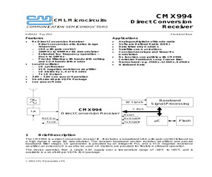
less systems up to and above 10 GHz. Table 1 describes the various packages and markings of the SMV1705 group of varactors. Table 1. Packaging and Marking Common Cathode Single Single SOT-23 SC-79 GreenTM SOD-882 GreenTM SMV1705-004LF GreenTM Marking: HY3 SMV1705-079LF Marking: Cathode SMV1705-040LF Marking: O LS = 1.4 nH LS = 0.7 nH LS = 0.45 nH SMV1705-004 Marking: CY3 The Pb-free symbol or "LF" in the part number denotes a lead-free, RoHS-compliant package unless otherwise noted as GreenTM. Tin/lead (Sn/Pb) packaging is not recommended for new designs. Skyworks Solutions, Inc. * Phone [781] 376-3000 * Fax [781] 376-3100 * sales@skyworksinc.com * www.skyworksinc.com 200076K * Skyworks Proprietary Information * Products and Product Information are Subject to Change Without Notice * March 13, 2013 1 DATA SHEET * SMV1705 SERIES VARACTORS Table 2. SMV1705 Series Absolute Maximum Ratings Parameter Symbol Minimum Maximum Units 12 V Reverse voltage VR Forward current IF 20 mA Power dissipation PDIS 25
 9 Pages, 510 KB, Original
CON2 VCON1 VCOP2 VCOP1 VCO Output Buffer Amplifier L1 should have a Q>30 L1 C1 C2 C3 CV2 CV1 R1 R2 Input from Loop Filter Figure 10 Example External Components - VCO External Tank Circuit L1 C1 C2 C3 8.2 nH (Note 1) 8.2 pF (Note 2) 22pF 22pF CV1 CV2 R1 R2 SMV1705-079LF SMV1705-079LF 10k 10k Note 1: Tolerance of 2% or better recommended Note 2: Tolerance of 5% or better recommended Table 11 Internal VCO Amplifier Tank Circuit for 440MHz Operation 2012 CML Microsystems Plc 15 D/994/12 Direct Conversion Receiver CMX994 Output to Tank Cct DO R2 C1 R1 C3 C2 Figure 11 Example External Components - PLL Loop Filter C1 C2 C3 150nF 1000nF 15nF R1 R2 1.5k 2.4k rd Table 12 3 Order Loop Filter Circuit Values 4.4 RESETN The RESETN pin generates a reset signal when low. The RESETN pin has an internal pull-up resistor of 100k connected to VDDIO. 2012 CML Microsystems Plc 16 D/994/12 Direct Conversion Receiver 5 CMX994 General Description The architecture of the CMX994 integrated circuit and related
 54 Pages, 1121 KB, Original