GF1J, GF1K, GF1M www.vishay.com Vishay General Semiconductor Surface Mount Glass Passivated Rectifier FEATURES * Superectifier structure for high reliability condition * Ideal for automated placement SUPERECTIFIER(R) * Low forward voltage drop * Low leakage current * High forward surge capability * Meets MSL level 1, per J-STD-020, LF maximum peak of 250 C * AEC-Q101 qualified DO-214BA (GF1) * Material categorization: For definitions of compliance please see www.vishay.com/doc?99912 TYPICAL APPLICATIONS For use in general purpose rectification of power supplies, inverters, converters and freewheeling diodes for consumer, automotive and telecommunication. PRIMARY CHARACTERISTICS IF(AV) 1.0 A VRRM 50 V, 100 V, 200 V, 400 V, 600 V, 800 V, 1000 V IFSM 30 A VF 1.1 V, 1.2 V IR 5.0 A TJ max. 175 C Package DO-214BA (GF1) Diode variations Single die MECHANICAL DATA Case: DO-214BA, molded epoxy over glass body Molding compound meets UL 94 V-0 flammability rating Base P/N-E3 - RoHS-compliant, commercial gra
 5 Pages, 105 KB, Original
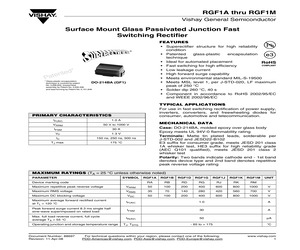
GF1J, RGF1K, RGF1M www.vishay.com Vishay General Semiconductor Surface Mount Glass Passivated Junction Fast Switching Rectifier FEATURES * Superectifier structure for high reliability condition * Ideal for automated placement * Fast switching for high efficiency Superectifier(R) * Low leakage current * High forward surge capability * Meets MSL level 1, per J-STD-020, LF maximum peak of 250 C * AEC-Q101 qualified available GF1 (DO-214BA) - Automotive ordering code: base P/NHE3 * Material categorization: for definitions of compliance please see www.vishay.com/doc?99912 TYPICAL APPLICATIONS For use in fast switching rectification of power supply, inverters, converters, and freewheeling diodes for consumer, automotive, and telecommunication. PRIMARY CHARACTERISTICS IF(AV) 1.0 A VRRM 50 V, 100 V, 200 V, 400 V, 600 V, 800 V, 1000 V IFSM 30 A VF 1.3 V trr 150 ns, 250 ns, 500 ns TJ max. 175 C Package GF1 (DO-214BA) Diode variations Single MECHANICAL DATA Case: GF1 (DO-214BA), molded epoxy over glass body
 5 Pages, 96 KB, Original
ied), meets JESD 201 class 2 whisker test Polarity: Color band denotes cathode end MAXIMUM RATINGS (TA = 25 C unless otherwise noted) PARAMETER SYMBOL Device marking code Maximum repetitive peak reverse voltage VRRM Maximum RMS voltage GF1A GF1B GF1D GF1G GF1J GF1K GF1M GA GB GD GG GJ GK GM UNIT 50 100 200 400 600 800 1000 V VRMS 35 70 140 280 420 560 700 V Maximum DC blocking voltage VDC 50 100 200 400 600 800 1000 V Maximum average forward rectified current at TL = 125 C IF(AV) 1.0 A Peak forward surge current 8.3 ms single half sine-wave superimposed on rated load IFSM 30 A TJ, TSTG - 65 to + 175 C Operating junction and storage temperature range Document Number: 88617 Revision: 30-Apr-08 For technical questions within your region, please contact one of the following: PDD-Americas@vishay.com, PDD-Asia@vishay.com, PDD-Europe@vishay.com www.vishay.com 1 GF1A thru GF1M Vishay General Semiconductor ELECTRICAL CHARACTERISTICS (TA = 25 C unless otherwise noted) PARAMETER TEST CONDITIONS Maximum inst
 4 Pages, 86 KB, Original
GF1J, RGF1K, RGF1M www.vishay.com Vishay General Semiconductor Surface Mount Glass Passivated Junction Fast Switching Rectifier FEATURES * Superectifier structure for high reliability condition * Ideal for automated placement * Fast switching for high efficiency Superectifier(R) * Low leakage current * High forward surge capability * Meets MSL level 1, per J-STD-020, LF maximum peak of 250 C * AEC-Q101 qualified available GF1 (DO-214BA) - Automotive ordering code: base P/NHE3 * Material categorization: for definitions of compliance please see www.vishay.com/doc?99912 TYPICAL APPLICATIONS For use in fast switching rectification of power supply, inverters, converters, and freewheeling diodes for consumer, automotive, and telecommunication. PRIMARY CHARACTERISTICS IF(AV) 1.0 A VRRM 50 V, 100 V, 200 V, 400 V, 600 V, 800 V, 1000 V IFSM 30 A VF 1.3 V trr 150 ns, 250 ns, 500 ns TJ max. 175 C Package GF1 (DO-214BA) Diode variations Single MECHANICAL DATA Case: GF1 (DO-214BA), molded epoxy over glass body
 4 Pages, 78 KB, Original
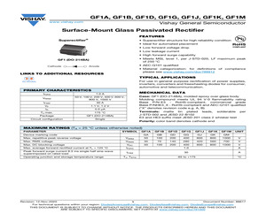
GF1J, GF1K, GF1M www.vishay.com Vishay General Semiconductor Surface Mount Glass Passivated Rectifier FEATURES * Superectifier structure for high reliability condition * Ideal for automated placement Superectifier(R) * Low forward voltage drop * Low leakage current * High forward surge capability * Meets MSL level 1, per J-STD-020, LF maximum peak of 250 C * AEC-Q101 qualified GF1 (DO-214BA) * Material categorization: for definitions of compliance please see www.vishay.com/doc?99912 TYPICAL APPLICATIONS For use in general purpose rectification of power supplies, inverters, converters and freewheeling diodes for consumer, automotive and telecommunication. PRIMARY CHARACTERISTICS IF(AV) 1.0 A VRRM 50 V, 100 V, 200 V, 400 V, 600 V, 800 V, 1000 V IFSM 30 A VF 1.1 V, 1.2 V IR 5.0 A TJ max. 175 C Package GF1 (DO-214BA) Circuit configuration Single MECHANICAL DATA Case: GF1 (DO-214BA), molded epoxy over glass body Molding compound meets UL 94 V-0 flammability rating Base P/N-E3 - RoHS-compliant, commerc
 5 Pages, 76 KB, Original
GF1J, RGF1K, RGF1M www.vishay.com Vishay General Semiconductor Surface Mount Glass Passivated Junction Fast Switching Rectifier FEATURES * Superectifier structure for high reliability condition * Ideal for automated placement * Fast switching for high efficiency Superectifier(R) * Low leakage current * High forward surge capability * Meets MSL level 1, per J-STD-020, LF maximum peak of 250 C * AEC-Q101 qualified available GF1 (DO-214BA) - Automotive ordering code: base P/NHE3 * Material categorization: for definitions of compliance please see www.vishay.com/doc?99912 TYPICAL APPLICATIONS For use in fast switching rectification of power supply, inverters, converters, and freewheeling diodes for consumer, automotive, and telecommunication. PRIMARY CHARACTERISTICS IF(AV) 1.0 A VRRM 50 V, 100 V, 200 V, 400 V, 600 V, 800 V, 1000 V IFSM 30 A VF 1.3 V trr 150 ns, 250 ns, 500 ns TJ max. 175 C Package GF1 (DO-214BA) Diode variations Single MECHANICAL DATA Case: GF1 (DO-214BA), molded epoxy over glass body
 4 Pages, 76 KB, Original
ctor AXIAL LEAD THRU-HOLE PART SURFACE MOUNT PART MicroSMP SMP GF1 SMA SMB SMC 1N3611GP ~ 1N3957GP 1N4001 ~ 1N4007 S1PB ~ S1PM S1A ~ S1M 1N4001GP ~ 1N4007GP GF1A ~ GF1M 1N4245 ~ 1N4249 GF1D ~ GF1M 1N4245GP ~ 1N4249GP GF1D ~ GF1M 1N4383GP ~ 1N4385GP GF1D ~ GF1J 1N4585GP, 1N4586GP GF1K, GF1M 1N4933 ~ 1N4937 RS1PB ~ RS1PJ RS1A ~ RS1J 1N4933GP ~ 1N4937GP RGF1A ~ RGF1J 1N4942 ~ 1N4948 RGF1D ~ RGF1M 1N4942GP ~ 1N4948GP RGF1D ~ RGF1M 1N5059GP ~ 1N5062GP RGF1D ~ RGF1K 1N5391 ~ 1N5399 S2A ~ S2M 1N5391GP ~ 1N5399GP S2A ~ S2M 1N5400 ~ 1N5408 S3A ~ S3M 1N5614GP ~ 1N5622GP GF1D ~ GF1M 1N5615GP ~ 1N5623GP RGF1D ~ RGF1M 1N5817 ~ 1N5819 SS12 ~ SS14 1N5820 ~ 1N5822 SS32 ~ SS34 BA157GP RGF1G BA158GP RGF1J EGP20A ~ EGP20G ES2A ~ ES2G ES3A ~ ES3G EGP30A ~ EGP30G FGP10B ~ FGP10D ESH1PB ~ ESH1PD EGF1B ~ EGF1D ESH1B ~ ESH1D GI500 ~ GI510 S3A ~ S3M GI850 ~ GI858 RS3A ~ RS3K GI910 ~ GI917 RS3A ~ RS3K GF1A ~ GF1M GP10A ~ GP10M GP15A ~ GP15M S2A ~ S2M GP20A ~ GP20J S2A ~ S2J GP30A ~ GP30M MPG06A ~
 1509 Pages, 20976 KB, Original
GF1J, GF1K, GF1M www.vishay.com Vishay General Semiconductor Surface-Mount Glass Passivated Rectifier FEATURES Superectifier (R) * Superectifier structure for high reliability condition * Ideal for automated placement * Low forward voltage drop * Low leakage current * High forward surge capability * Meets MSL level 1, per J-STD-020, LF maximum peak of 250 C GF1 (DO-214BA) Cathode * AEC-Q101 qualified Anode * Material categorization: for definitions of compliance please see www.vishay.com/doc?99912 LINKS TO ADDITIONAL RESOURCES TYPICAL APPLICATIONS 3D 3D For use in general purpose rectification of power supplies, inverters, converters and freewheeling diodes for consumer, automotive and telecommunication. 3D Models PRIMARY CHARACTERISTICS MECHANICAL DATA IF(AV) 1.0 A VRRM 50 V, 100 V, 200 V, 400 V, 600 V, 800 V, 1000 V IFSM 30 A VF 1.1 V, 1.2 V IR 5.0 A TJ max. 175 C Package GF1 (DO-214BA) Circuit configuration Single Case: GF1 (DO-214BA), molded epoxy over glass body Molding compound meets UL 94
 4 Pages, 84 KB, Original
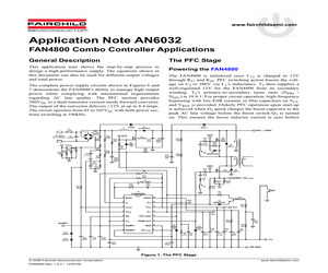
4 VRMS VCC 13 5 SS PFC OUT 12 6 VDC PWM OUT 11 10 7 RAMP1 GND 8 RAMP2 DC ILIMIT D4 MMBZ5245B VREF R13 10k VCC R11 845k D8 MBRS 140 9 C31 1nF C10 15uF R16 10k D10 MBRS 140 R8 2.37k C19 1uF Q4 MMBT3904 VFB D12 1N5401 C26 100nF R20B 2.2 R19 220 FAN4800 1 D6 RGF1J RAMP2 / DC ILIMIT R15 3 C7 NOT USED C6 1.5nF R12 71.5k Q3 FQPF6N50 C20 1uF R10 6.2k R31 100 T2 R14 33 R6 41.7k D13 1N5401 D5 RGF1J R28 240 C30 330uF 25V C2 0.47uF Q2 FQPF 6N50 R17 33 R7A 178k C25 0.1uF R1B 500k R3 110k Q2G C4 10nF R21 22 R2B 453k C3 0.1uF D3 RGF1J D1 ISL9R460P2 Q1 FQPF9N50 R27 75k ISENSE R5D R5C 1.2 R5B 1.2 R5A 1.2 1.2 The FAN4800 is initialized once C12 is charged to 13V through R27 and R28. PFC switching action boosts the voltage on C5 to 380V via L1's inductance. T2 then supplies a well-regulated 13V for the FAN4800 from its secondary winding. T2's primary-to-secondary turns ratio (NPRI / NSEC) is 18.8:1. For proper circuit operation, high-frequency bypassing with low-ESR ceramic or film capacit
 10 Pages, 444 KB, Original
isker test Polarity: Two bands indicate cathode end - 1st band denotes device type and 2nd band denotes repetitive peak reverse voltage rating MAXIMUM RATINGS (TA = 25 C unless otherwise noted) PARAMETER SYMBOL Device marking code RGF1A RGF1B RGF1D RGF1G RGF1J RGF1K RGF1M UNIT RA RB RD RG RJ RK RM Maximum repetitive peak reverse voltage VRRM 50 100 200 400 600 800 1000 V Maximum RMS voltage VRMS 35 70 140 280 420 560 700 V Maximum DC blocking voltage VDC 50 100 200 400 600 800 1000 V Maximum average forward rectified current at TL = 120 C IF(AV) 1.0 A Peak forward surge current 8.3 ms single half sine-wave superimposed on rated load IFSM 30 A Max. full load reverse current, full cycle average TA = 55 C IR(AV) 50 A TJ, TSTG - 65 to + 175 C Operating junction and storage temperature range Document Number: 88697 Revision: 11-Apr-08 For technical questions within your region, please contact one of the following: PDD-Americas@vishay.com, PDD-Asia@vishay.com, PDD-Europe@vishay.com www.vishay.com 1 RGF1
 4 Pages, 87 KB, Original
GF1J, GF1K, GF1M www.vishay.com Vishay General Semiconductor Surface Mount Glass Passivated Rectifier FEATURES * Superectifier structure for high reliability condition * Ideal for automated placement SUPERECTIFIER(R) * Low forward voltage drop * Low leakage current * High forward surge capability * Meets MSL level 1, per J-STD-020, LF maximum peak of 250 C * AEC-Q101 qualified DO-214BA (GF1) * Material categorization: For definitions of compliance please see www.vishay.com/doc?99912 TYPICAL APPLICATIONS For use in general purpose rectification of power supplies, inverters, converters and freewheeling diodes for consumer, automotive and telecommunication. PRIMARY CHARACTERISTICS IF(AV) 1.0 A VRRM 50 V, 100 V, 200 V, 400 V, 600 V, 800 V, 1000 V IFSM 30 A VF 1.1 V, 1.2 V IR 5.0 A TJ max. 175 C Package DO-214BA (GF1) Diode variations Single die MECHANICAL DATA Case: DO-214BA, molded epoxy over glass body Molding compound meets UL 94 V-0 flammability rating Base P/N-E3 - RoHS-compliant, commercial gra
 4 Pages, 82 KB, Original
GF1J, RGF1K, RGF1M www.vishay.com Vishay General Semiconductor Surface Mount Glass Passivated Junction Fast Switching Rectifier FEATURES SUPERECTIFIER(R) * Superectifier structure for high reliability condition * Ideal for automated placement * Fast switching for high efficiency * Low leakage current * High forward surge capability * Meets MSL level 1, per J-STD-020, LF maximum peak of 250 C DO-214BA (GF1) * AEC-Q101 qualified PPRIMARY CHARACTERISTICS * Material categorization: For definitions of compliance please see www.vishay.com/doc?99912 IF(AV) 1.0 A VRRM 50 V, 100 V, 200 V, 400 V, 600 V, 800 V, 1000 V IFSM 30 A VF 1.3 V trr 150 ns, 250 ns, 500 ns TJ max. 175 C Package DO-214BA (GF1) Diode variations Single MECHANICAL DATA Case: DO-214BA, molded epoxy over glass body Molding compound meets UL 94 V-0 flammability rating Base P/N-E3 - RoHS-compliant, commercial grade Base P/NHE3 - RoHS-compliant, AEC-Q101 qualified Terminals: Matte tin plated leads, solderable per J-STD-002 and JESD 22-B102 E3
 4 Pages, 74 KB, Original
GF1J, GF1K, GF1M www.vishay.com Vishay General Semiconductor Surface Mount Glass Passivated Rectifier FEATURES * Superectifier structure for high reliability condition * Ideal for automated placement SUPERECTIFIER(R) * Low forward voltage drop * Low leakage current * High forward surge capability * Meets MSL level 1, per J-STD-020, LF maximum peak of 250 C * AEC-Q101 qualified DO-214BA (GF1) * Material categorization: For definitions of compliance please see www.vishay.com/doc?99912 TYPICAL APPLICATIONS For use in general purpose rectification of power supplies, inverters, converters and freewheeling diodes for consumer, automotive and telecommunication. PRIMARY CHARACTERISTICS IF(AV) 1.0 A VRRM 50 V, 100 V, 200 V, 400 V, 600 V, 800 V, 1000 V IFSM 30 A VF 1.1 V, 1.2 V IR 5.0 A TJ max. 175 C Package DO-214BA (GF1) Diode variations Single die MECHANICAL DATA Case: DO-214BA, molded epoxy over glass body Molding compound meets UL 94 V-0 flammability rating Base P/N-E3 - RoHS-compliant, commercial gra
 4 Pages, 79 KB, Original
GF1J, GF1K, GF1M www.vishay.com Vishay Semiconductors Surface Mount Glass Passivated Rectifier FEATURES * Superectifier structure for high reliability condition * Ideal for automated placement SUPERECTIFIER(R) * Low forward voltage drop * Low leakage current * High forward surge capability * Meets MSL level 1, per J-STD-020, LF maximum peak of 250 C * AEC-Q101 qualified DO-214BA (GF1) * Material categorization: For definitions of compliance please see www.vishay.com/doc?99912 TYPICAL APPLICATIONS For use in general purpose rectification of power supplies, inverters, converters and freewheeling diodes for consumer, automotive and telecommunication. PRIMARY CHARACTERISTICS IF(AV) 1.0 A VRRM 50 V, 100 V, 200 V, 400 V, 600 V, 800 V, 1000 V IFSM 30 A VF 1.1 V, 1.2 V IR 5.0 A TJ max. 175 C Package DO-214BA (GF1) Diode variations Single die MECHANICAL DATA Case: DO-214BA, molded epoxy over glass body Molding compound meets UL 94 V-0 flammability rating Base P/N-E3 - RoHS-compliant, commercial grade Base
 4 Pages, 74 KB, Original
23 100nF R24 1.2k C21 2200uF 25V R22 8.66k R18 220 12V RETURN 12V RET 12V, 100W 12V L1; PREMIER MAGNETICS TDS-1047 L2; PREMIER MAGNETICS VTP-05007 T1; PREMIER MAGNETICS PMGO-03 T2; PREMIER MAGNETICS TSO-735 VDC / +380V D11A MBR2545CT RAMP2 / DC ILIMIT D6 RGF1J D5 RGF1J Q3 FQPF6N50 Q2 FQPF 6N50 D4 MMBZ5245B R19 220 Q3G D7 MMBZ5245B R14 33 T1B R30 4.7k Q2G C25 0.1uF R17 33 D3 RGF1J FAN4800 Low Start-Up Current PFC/PWM Controller Combos Typical Application Circuit Figure 13. Voltage-Mode Application FAN4800 Rev. 1.0.5 (c) 2005 Fairchild Semiconductor Corporation 17 www.fairchildsemi.com D13 1N5401 D12 1N5401 RAMP1 R5D R5C 1.2 R5B 1.2 R5A 1.2 1.2 ISENSE AC INPUT C1 85 TO 265Vac 0.68uF F1 3.15A R31 100 C26 100nF C3 0.1uF C19 1uF R4 15.4k C2 0.47uF R3 110k R2B 453k R2A 453k BR1 4A, 600V KBL06 C18 470pF R1B 500k R1A 500k 8 7 6 5 4 3 2 1 R21 22 RAMP2 RAMP1 VDC SS VRMS ISENSE IAC U1 C7 NOT USED C6 1.5nF R29 61.9k DC ILIMIT GND PWM OUT PFC OUT VCC VREF VFB VEAO FAN4800 R12 71.5k R
 20 Pages, 268 KB, Original