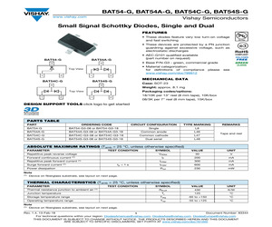
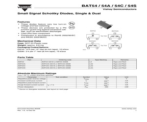
BAT54C-G, BAT54S-G www.vishay.com Vishay Semiconductors Small Signal Schottky Diodes, Single and Dual FEATURES * These diodes feature very low turn-on voltage and fast switching * These devices are protected by a PN junction guardring against excessive voltage, such as electrostatic discharges * AEC-Q101 qualified available (part number on request) BAT54A-G BAT54-G * Base P/N-G3 - green, commercial grade 3 3 * Material categorization: for definitions of compliance please see www.vishay.com/doc?99912 Top View 1 1 2 BAT54C-G 2 MECHANICAL DATA BAT54S-G 3 Case: SOT-23 3 Weight: approx. 8.1 mg Packaging codes/options: Top View 1 2 1 18/10K per 13" reel (8 mm tape), 10K/box 2 08/3K per 7" reel (8 mm tape), 15K/box DESIGN SUPPORT TOOLS click logo to get started Models Available PARTS TABLE PART ORDERING CODE BAT54-G BAT54-G3-08 or BAT54-G3-18 CIRCUIT CONFIGURATION TYPE MARKING Single L8 BAT54A-G BAT54A-G3-08 or BAT54A-G3-18 Common anode L46 BAT54C-G BAT54C-G3-08 or
 4 Pages, 100 KB, Original
BAT54C-G, BAT54S-G www.vishay.com Vishay Semiconductors Small Signal Schottky Diodes, Single and Dual FEATURES * These diodes feature very low turn-on voltage and fast switching * These devices are protected by a PN junction guardring against excessive voltage, such as electrostatic discharges * AEC-Q101 qualified available (part number on request) BAT54A-G BAT54-G * Base P/N-G3 - green, commercial grade 3 3 * Material categorization: for definitions of compliance please see www.vishay.com/doc?99912 Top View 1 1 2 BAT54C-G 2 MECHANICAL DATA BAT54S-G 3 Case: SOT-23 3 Weight: approx. 8.1 mg Packaging codes/options: Top View 1 2 1 18/10K per 13" reel (8 mm tape), 10K/box 2 08/3K per 7" reel (8 mm tape), 15K/box DESIGN SUPPORT TOOLS click logo to get started Models Available PARTS TABLE PART ORDERING CODE BAT54-G BAT54-G3-08 or BAT54-G3-18 CIRCUIT CONFIGURATION TYPE MARKING Single L8 BAT54A-G BAT54A-G3-08 or BAT54A-G3-18 Common anode L46 BAT54C-G BAT54C-G3-08 or
 5 Pages, 105 KB, Original
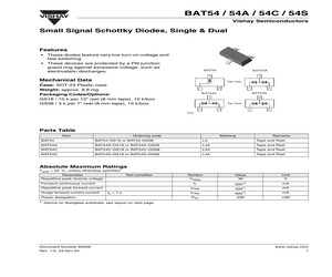
BAT54C-G, BAT54S-G www.vishay.com Vishay Semiconductors Small Signal Schottky Diodes, Single and Dual FEATURES * These diodes feature very low turn-on voltage and fast switching * These devices are protected by a PN junction guardring against excessive voltage, such as electrostatic discharges * AEC-Q101 qualified * Base P/N-G3 - green, commercial grade BAT54A-G BAT54-G * Material categorization: For definitions of compliance please see www.vishay.com/doc?99912 3 3 Top View MECHANICAL DATA 1 1 2 BAT54C-G 2 Case: SOT-23 Weight: approx. 8.1 mg BAT54S-G 3 Packaging codes/options: 3 18/10K per 13" reel (8 mm tape), 10K/box Top View 1 2 08/3K per 7" reel (8 mm tape), 15K/box 1 2 PARTS TABLE PART ORDERING CODE BAT54-G INTERNAL CONSTRUCTION TYPE MARKING BAT54-G3-08 or BAT54-G3-18 Single diode L8 BAT54A-G BAT54A-G3-08 or BAT54A-G3-18 Dual diodes common anode L46 BAT54C-G BAT54C-G3-08 or BAT54C-G3-18 Dual diodes common cathode L47 BAT54S-G BAT54S-G3-08 o
 4 Pages, 91 KB, Original
BAT54C-G, BAT54S-G www.vishay.com Vishay Semiconductors Small Signal Schottky Diodes, Single and Dual FEATURES * These diodes feature very low turn-on voltage and fast switching * These devices are protected by a PN junction guardring against excessive voltage, such as electrostatic discharges * AEC-Q101 qualified available (part number on request) BAT54A-G BAT54-G * Base P/N-G3 - green, commercial grade 3 3 * Material categorization: for definitions of compliance please see www.vishay.com/doc?99912 Top View 1 1 2 BAT54C-G 2 MECHANICAL DATA BAT54S-G 3 Case: SOT-23 3 Weight: approx. 8.1 mg Packaging codes/options: Top View 1 2 1 18/10K per 13" reel (8 mm tape), 10K/box 2 08/3K per 7" reel (8 mm tape), 15K/box DESIGN SUPPORT TOOLS click logo to get started Models Available PARTS TABLE PART ORDERING CODE BAT54-G BAT54-G3-08 or BAT54-G3-18 CIRCUIT CONFIGURATION TYPE MARKING Single L8 BAT54A-G BAT54A-G3-08 or BAT54A-G3-18 Common anode L46 BAT54C-G BAT54C-G3-08 or
 4 Pages, 98 KB, Original
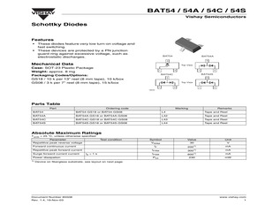
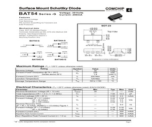
5V 150 OHM R312 VSI 1 2 1 2 FB304 4 GIN NC VCC5V HSI RIN 100 1/16W R309 100 1/16W R310 150 1/16W R311 1K 1/16W VCC5V ST_DET1 6 HSYNC 4 PC5V VSYNC 4 1 3 15 FB301 2 14 6 6 R327 75 1/16W 13 RXD TXD 3 12 3 11 R326 75 1/16W CN301 DB15 1 6 2 7 3 8 4 9 5 10 D304 BAT54C-GS08 D320 MLL5232B 5.6V R313 2.2K 1/16W C311 R314 C312 33pF 10K 1/16W 220pF D317 MLL5232B 5.6V 3 D319 MLL5232B 5.6V R317 R318 20K 1/16W R315 R316 100 1/16W 100 1/16W CN302 6 6 100 1/16W NC 100 1/16W NC DVI5V D314 D315 D316 LL5232B 5.6V 5% NC LL5232B 5.6V 5% NC LL5232B 5.6V 5% NC R321 10K 1/16W NC 100 1/16W NC R323 0.1uF NC 20K 1/16W NC D311 BAV99 NC D312 BAV99 NC 3 D310 BAV99 NC ST_DET2 6 C314 3 D309 BAV99 NC 3 3 3 D308 BAV99 NC DVI5V D305 BAT54C-GS08 NC R322 18 17 10 9 2 1 13 12 5 4 21 20 23 24 D307 BAV99 NC 0.1uF 1 2 R319 R320 D306 BAV99 NC 1 2 3 4 3 CLK_DDC2 DAT_DDC2 JACK NC A0 A1 A2 GND DDC_DAT DDC_CLK VCC5V 11 3 19 22 VCC WP SCL SDA AT24C02N-10SC D318 MLL5232B 5.6V 3 DAT0+ DAT0DAT1+ DAT1DAT2+ DAT2DAT3+ DAT3DAT4+ DAT4DAT5
 51 Pages, 859 KB, Original
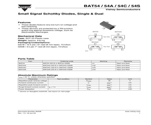
0 k/box GS08 / 3 k per 7" reel (8 mm tape), 15 k/box 1 1 2 2 BAT54C BAT54S 3 3 Top View 1 2 1 2 18034 Parts Table Part Ordering code Marking Remarks BAT54 BAT54-GS18 or BAT54-GS08 L4 Tape and Reel BAT54A BAT54A-GS18 or BAT54A-GS08 L42 Tape and Reel BAT54C BAT54C-GS18 or BAT54C-GS08 L43 Tape and Reel BAT54S BAT54S-GS18 or BAT54S-GS08 L44 Tape and Reel Absolute Maximum Ratings Tamb = 25 C, unless otherwise specified Parameter Test condition Repetitive peak reverse voltage Forward continuous current Unit 30 V IFRM tp < 1 s Power dissipation 1) Value VRRM IF Repetitive peak forward current Surge forward current current Symbol IFSM Ptot 200 1) mA 300 1) mA 600 1) 230 mA mW Device on fiberglass substrate, see layout on next page. Document Number 85508 Rev. 1.6, 24-Nov-04 www.vishay.com 1 BAT54 / 54A / 54C / 54S Vishay Semiconductors Thermal Characteristics Tamb = 25 C, unless otherwise specified Parameter Test condition Symbol Value Unit RthJA 4301) C/W Tj = Tstg - 65 to + 150 C TS - 65 to
 5 Pages, 114 KB, Original
0 k/box GS08 / 3 k per 7" reel (8 mm tape), 15 k/box 1 1 2 2 BAT54C BAT54S 3 3 Top View 1 2 1 2 18034 Parts Table Part Ordering code Marking Remarks BAT54 BAT54-GS18 or BAT54-GS08 L4 Tape and Reel BAT54A BAT54A-GS18 or BAT54A-GS08 L42 Tape and Reel BAT54C BAT54C-GS18 or BAT54C-GS08 L43 Tape and Reel BAT54S BAT54S-GS18 or BAT54S-GS08 L44 Tape and Reel Absolute Maximum Ratings Tamb = 25 C, unless otherwise specified Parameter Test condition Repetitive peak reverse voltage Forward continuous current Repetitive peak forward current Surge forward current current tp < 1 s Power dissipation 1) Symbol Value Unit VRRM 30 V IF 2001) mA IFRM 3001) mA IFSM 1) Ptot 600 230 mA mW Device on fiberglass substrate, see layout on next page. Document Number 85508 Rev. 1.4, 19-Nov-03 www.vishay.com 1 BAT54 / 54A / 54C / 54S VISHAY Vishay Semiconductors Thermal Characteristics Tamb = 25 C, unless otherwise specified Parameter Test condition Symbol Thermal resistance junction to ambiant air Junction temper
 5 Pages, 80 KB, Original
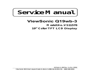
 U5 1 2 A0 3 A1 4 A2 GND 8 VCC 7 /WC 6 SCL 5 SDA 24C512 / NP E2PROM_5V U4 1 2 A0 3 A1 4 A2 GND 8 VCC 7 /WC 6 SCL 5 SDA SDA 10K R4 R3 13 . SW2F . . SW2E . . SW2D . . SW2C . . SW2B . . SW2A . . SW2G . 12 IAP_SCL 10 8 6 4 c u d o r 14 24C512 / NP DDC_5V 1 D1 BAT54C-GS08 . SW1C . 2 8 VCC 7 /WC 6 SCL 5 SDA 24C512 / NP DSUB_5 2 B1 BATTERY 6 1 5 U3 1 2 A0 3 A1 4 A2 GND 3 3 C BAT54C A A 1 2 3 DSUB_10 2 D2 BAT54C-GS08 U2 1 2 A0 3 A1 4 A2 GND 8 VCC 7 /WC 6 SCL 5 SDA 1 2 3 4 s ( t c u d o r eP 4 HEADER IAP_SDA P e et O ) 24C512 / NP JP1 l o bs 1 ) s t( 2 U1 1 2 A0 3 A1 4 A2 GND 8 VCC 7 /WC 6 SCL 5 SDA 24C512 E2PROM_5V IAP_SCL IAP_SDA R11/NP 0ohm 2.54mmpitch t e ol s b O June 2004 This is preliminary information on a new product. Details are subject to change without notice. 9/11 AN1991 4. LAYOUT Top layer ) s t( c u d o r l o bs P e et O ) Bottom layer s ( t c u d o r eP t e ol s b O June 2004 This is preliminary information on a new product. Details are subject to change without notice. 10/11
 11 Pages, 243 KB, Original
/box GS08 / 3 k per 7" reel (8 mm tape), 15 k/box 1 2 2 BAT54C BAT54S 3 3 Top View 1 2 1 2 18034 Parts Table Part Ordering code Type Marking Remarks BAT54 BAT54-GS18 or BAT54-GS08 L4 Tape and Reel BAT54A BAT54A-GS18 or BAT54A-GS08 L42 Tape and Reel BAT54C BAT54C-GS18 or BAT54C-GS08 L43 Tape and Reel BAT54S BAT54S-GS18 or BAT54S-GS08 L44 Tape and Reel Absolute Maximum Ratings Tamb = 25 C, unless otherwise specified Parameter Test condition Repetitive peak reverse voltage Forward continuous current Unit 30 V IFRM tp < 1 s Power dissipation 1) Value VRRM IF Repetitive peak forward current Surge forward current current Symbol IFSM Ptot 200 1) mA 300 1) mA 600 1) 230 mA mW Device on fiberglass substrate, see layout on next page. Document Number 85508 Rev. 1.6, 12-Dec-05 www.vishay.com 1 BAT54 / 54A / 54C / 54S Vishay Semiconductors Thermal Characteristics Tamb = 25 C, unless otherwise specified Parameter Test condition Symbol Value Unit RthJA 4301) K/W Tj 125 C Tstg - 65 to + 150 C Therma
 6 Pages, 310 KB, Original
XG 1000 M CA 16X25 3300 F/35 V C65,C64 Yageo 2 SC035M3300A5F-1836 BAS16 D15,D5,D6,D22,D7,D24,D21,D19 ,D14,D11,D23,D18,D13,D3,D20, D9,D4,D17,D16,D12,D10,D8 Fairchild 22 BAS16 BAT54 D46 Vishay 1 BAT54-GS18 BAT54A D41 Vishay 1 BAT54A-GS18 BAT54C D39 Vishay 1 BAT54C-GS18 BAT54S D40 Vishay 1 BAT54S-GS18 BC846B Q13 Infineon technologies 1 BC846B BC857B Q12,Q14 Fairchild 2 BC857B BDX53C Q16 STMicroelectronics 1 BDX53C BPT-14 B1 Bestar electronics industry 1 BPT-14 B600C1500 BR2 DC Components 1 B600C1500 BZV55C10 D32,D31 Central semiconductor, Microsemi 2 BZV55C10 BZV55C20 D34,D33 Central semiconductor, Microsemi 2 BZV55C20 BZV55C20 D35 Central semiconductor, Microsemi 1 BZV55C20 BZV55C22 D50 Central semiconductor, Microsemi 1 BZV55C22 BZV55C75 D49,D36 Central semiconductor, Microsemi 2 BZV55C75 Heatsink RAD5,RAD6 Fideltronik 2 40X53X20 (MUP831) Heatsink RAD13,RAD10,RAD9,RAD7, RAD8 Fideltronik 5 LM-317 (MUPS190) Heatsink RAD12,RAD4,RAD1,RAD3, RAD11,RAD2 Fischer elektronik 6 SK145 37,5 STS TO220 IDC10 J15
 66 Pages, 1032 KB, Original
tion SOT-23 .119 (3.0) .110 (2.8) .020 (0.5) .056 (1.40) .047 (1.20) 2 1 CATHODE 1 3 1 CATHODE ANODE 3 .037(0.95) .037(0.95) ANODE 2 CATHODE ANODE ANODE CATHODE 1 CATHODE 3 1 3 2 CATHODE .006 (0.15)max. BAT54A-G BAT54-G Top View 3 .020 (0.5) 2 ANODE ANODE BAT54C-G .044 (1.10) .035 (0.90) Case: SOT-23, Molded Plastic Terminals: Solderable per MIL-STD-202, Method 208 Polarity: See Diagrams Below Weight: 0.008 grams (approx.) Mounting Position: Any .006 (0.15) .002 (0.05) Mechanical data .103 (2.6) .086 (2.2) .020 (0.5) CATHODE Dimensions in inches (millimeters) BAT54S-G Maximum Ratings (TA = 125C unless otherwise noted) Rating Reverse Voltage Forward Power Dissipation @ TA = 25C Derate above 25C Forward Current (DC) Symbol VR IF Value 30 225 1.8 200 Max Units Volts mW mW/C mA Junction Temperature TJ 125 Max C Storage Temperature Range Tstg -55 to +150 C PF Electrical Characterics (TA = 25C unless otherwise noted) (EACH DIODE) Parameter Symbol Min V(BR)R Reverse Breakdown Voltage (IR = 10 mA) 30 CT
 3 Pages, 66 KB, Original
W 150 OHM 100 1/16W R312 D320 MLL5232B 5.6V R313 C311 R314 C312 2.2K 1/16W 33pF 10K 1/16W 220pF 100 1/16W NC 100 1/16W NC R311 1K 1/16W DVI5V D314 D315 D316 LL5232B 5.6V 5% NC LL5232B 5.6V 5% NC LL5232B 5.6V 5% NC VCC5V ST_DET1 6 HSYNC 4 VSYNC 4 PC5V D304 BAT54C-GS08 R317 R318 10K 1/16W 100 1/16W NC C313 U301 10K 1/16W 8 7 6 5 100 1/16W 100 1/16W VCC WP SCL SDA 0.1uF 1 2 3 4 A0 A1 A2 GND AT24C02N-10SC 6 6 DDC_DAT DDC_CLK VCC5V DVI5V D305 BAT54C-GS08 NC ST_DET2 6 C314 R323 R324 10K 1/16W NC 10K 1/16W NC 0.1uF NC JACK NC 4 R321 10K 1/16W NC R322 18 17 10 9 2 1 13 12 5 4 21 20 23 24 4 GNDB D317 MLL5232B 5.6V //w DAT0+ DAT0DAT1+ DAT1DAT2+ DAT2DAT3+ DAT3DAT4+ DAT4DAT5+ DAT5clk+ clk- 11 3 19 22 R319 R320 150 1/16W p: 1/3shield 2/4shield 0/5shield clk shield D318 MLL5232B 5.6V CLK_DDC2 DAT_DDC2 100 1/16W R310 htt R G B RGB GND HSYNC VSYNC SYNC GND DDC SCL DDC SDA +5V HPD 4 GNDG R315 R316 CN302 D321 MLL5232B 5.6V R309 ww CLK_DDC DAT_DDC 25 26 27 29 28 8 15 6 7 14 16 GNDR 2 VSI 4 .w jel FB304
 56 Pages, 1470 KB, Original
R6 1u 4.7K 50 BKLT_ADJ 4 MMBT3904 2 5/4 modified 1 C FB2 B1206 +5V B 2 5/17 del C8 MLB-201209-0220P-N2 C0603 1N4148 DVI5V HEADER5X2 F1 PC5V1 FB3 B1206 2 R9 R10 0 0 +5V MLB-201209-0220P-N2 2 C9 0.1uF TC2 220uF/25V C0603 3,4,6 +5V D4 VCC5V D3 SSM12L SOT-263 BAT54C-GS08U2 S5 R11 10K R12 S S S G D D D D 8 7 6 5 C14 0.1uF 100uF/16V Si9435-SO8 C13 0.1uF 0.1uF APPROVE BY Q4 1 MMBT3904 C16 H1 H4 CHECK BY PREPARE BY H3 8 7 6 5 4 TP TP 1 2 3 5 4 1 2 3 5 4 8 7 6 8 7 6 5 4 5 4 Title 200-100-2A1D-BH TP Size B 1 2 3 1 2 3 5 4 8 7 6 8 7 6 8 7 6 0.1uF Date: 5 4 A 2 4K7 B C12 3 R13 A VCC3.3 4,5 C10 + C15 220uF/16V 0.1uF 4 PANELVCC_EN 4 VLCD 5 100 + TC3 VO VO 0.1uF U3 1 2 3 4 1 ADJ VLCD 1 2 VI C11 1 2 3 +5V 3 VCC5V 2 1 S3 2 3 1 2 3 VCC3V3_PANEL +12V 6 VCC3.3 LT1084-33 3 +12V 9/14 modified S1 and S2 change to S3 and S5 B 100 PC5V1 3 +12V 1 C R8 3 DVI5V 24V/5A + 2K CHT2907 D2 C7 0.1uF TC1 220uF/25V R7 E + 1N4148 Q3 1 C 4.7uF/16V D1 BL_CTRL BRT_LEVEL VCC1.8 4 + C6 CN1 10 9 8 7 6 5 4 3 2 1 VCC1.8 3 2 Document Number R
 27 Pages, 1017 KB, Original
D5 Z5.6/NC 100/6 R17 2 D4 IN-V R15 2.2K/6 1 VGA _SDA_O 1 IN-V 1 IN -H C88 0.1uF/6/NC 3 2 BLUE +IN 2 GRE EN+IN 3 2 RED+ IN 3 33pF/6 D3 DAN217K/NC C87 0.1uF/6/NC C86 0.1uF/6/NC D2 DAN217K/NC HSYNC 5 C11 2.2K/6 1 1 1 R14 D1 DAN217K/NC 0.047uF/6 U7 0/6/NC D32 BAT54C-GS08 DDCD_SCL DDCD_SDA DDC_VCC CN3 8 7 6 5 VCC WP SCL SDA 24C02 A0 A1 A2 GND 1 2 3 4 C101 0.1uF/6 Q13 SCL-DD DC SDA-DDDC R104 B E R- 5 R+ 5 4.7K/6/NC 5 DDC_VCC DDC_VCC PMBS3904/NC R20 220/6/NC RX1RX1+ R22 R23 10/6 10/6 SCL-DD DC R24 SDA-DDDC R25 DVI_5V 100/6 100/6 DDCD_SCL 5 DDCD_SDA 5 220/6/NC 1 10K/6 RX0RX0+ R27 R28 10/6 10/6 1 R119 R21 10K/6 10K/6 G- 5 G+ 5 D12 B- 5 B+ 5 D13 Z5.6/NC Z5.6/NC 2 R118 R26 HPD_Ctrl 2 17 18 19 20 21 22 23 24 10/6 10/6 R120 220/6/NC RXC+ RXC- R29 R30 10/6 10/6 1 1 2 DVI-I RX0+ 3 10K/6/NC 10K/6/NC D16 DAN217K/NC C95 0.1uF/6/NC 3 2 RX0- D15 DAN217K/NC C93 0.1uF/6/NC 26 1 C13 0.1uF/6NC VCC3.3 D14 DAN217K/NC CLK+ 5 CLK- 5 R106 R107 RXC+ D17 DAN217K/NC 3 RXC- 3 C96 0.1uF/6/NC RX0RX0+ GND RX5RX5+ GND RXC+ RXC- R18
 70 Pages, 2993 KB, Original
0 k/box GS08 / 3 k per 7" reel (8 mm tape), 15 k/box 1 1 2 2 BAT54C BAT54S 3 3 Top View 1 2 1 2 18034 Parts Table Part Ordering code Marking Remarks BAT54 BAT54-GS18 or BAT54-GS08 L4 Tape and Reel BAT54A BAT54A-GS18 or BAT54A-GS08 L42 Tape and Reel BAT54C BAT54C-GS18 or BAT54C-GS08 L43 Tape and Reel BAT54S BAT54S-GS18 or BAT54S-GS08 L44 Tape and Reel Absolute Maximum Ratings Tamb = 25 C, unless otherwise specified Parameter Test condition Repetitive peak reverse voltage Forward continuous current Repetitive peak forward current Surge forward current current tp < 1 s Power dissipation 1) Symbol Value Unit VRRM 30 V IF 2001) mA IFRM 3001) mA IFSM 1) Ptot 600 230 mA mW Device on fiberglass substrate, see layout on next page. Document Number 85508 Rev. 1.5, 18-Jun-04 www.vishay.com 1 BAT54 / 54A / 54C / 54S VISHAY Vishay Semiconductors Thermal Characteristics Tamb = 25 C, unless otherwise specified Parameter Test condition Symbol Thermal resistance junction to ambiant air Junction temper
 5 Pages, 81 KB, Original