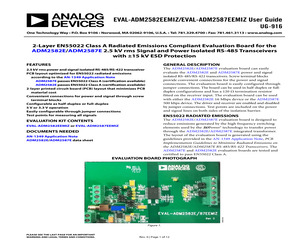
power delivery circuit in close proximity to the ADM2587E/ADM2582E device, so the VCC trace is as short as possible. The EVAL-ADM2582EEMIZ and EVAL-ADM2587EEMIZ PCB has a power delivery circuit located at the bottom of the PCB with a short trace from the ADP667ARZ regulator output to VCC (Pin 8). This layout example minimizes the loop area in which high frequency current can flow. An increase in the loop area results in an increase in the emissions levels. EN55022 RADIATED EMISSIONS TEST RESULTS The ADM2587E evaluation board is tested and certified to pass EN55022 Class A with >6 dbV margin. The ADM2582E evaluation board is tested and certified to pass EN55022 Class A. EN55022 Certification documents for the EVAL-ADM2582EEMIZ and EVAL-ADM2587EEMIZ evaluation boards are available to customers upon request from Analog Devices, Inc. Table 3 provides a summary of the capability of the EVALADM2582EEMIZ and EVAL-ADM2587EEMIZ evaluation boards. All EN55022 radiated emissions tests are performed with th
 12 Pages, 480 KB, Original
ower delivery circuit in close proximity to the ADM2582E/ADM2587E device, so that the VCC trace is as short as possible. The EVAL-ADM2582EEBZ and EVALADM2587EEBZ PCB has a power delivery circuit located at the bottom of the PCB with a short trace from the ADP667ARZ regulator output to VCC (Pin 8). This layout example minimizes the loop area in which high frequency current can flow. An increase in the loop area results in an increase in the emissions levels. Table 2. PCB Stack Up Primary VCC Side Layer 1: Ground 1 plane Layer 1: Ground 1 plane Layer 3: VCC plane Layer 4: Ground 1 plane Secondary VISO Side Layer 1: Ground 2 plane Layer 2: Ground 2 plane Layer 3: Ground 2 plane (overlap stitching capacitor) Layer 4: Ground 2 plane Table 3. EN55022 Test Results Summary Device ADM2582E ADM2582E ADM2587E ADM2587E Configuration 3.3 V VCC, 16 Mbps, 60 load 5.0 V VCC, 16 Mbps, 60 load 3.3 V VCC, 500 kbps, 60 load 5.0 V VCC, 500 kbps, 60 load EN55022 Class B Result Pass (with 4.7 dB V/m margin) Pass (with
 13 Pages, 460 KB, Original
S FOR REFERENCE ONLY AND ARE NOT APPROPRIATE FOR USE IN DESIGN. 012407-A 8 4.00 (0.1574) 3.80 (0.1497) Figure 17. 8-Lead Standard Small Outline Package [SOIC_N] Narrow Body (R-8) Dimensions shown in millimeters and (inches) ORDERING GUIDE Model1 ADP667ANZ ADP667ARZ ADP667ARZ-REEL7 1 Temperature Range -40C to +85C -40C to +85C -40C to +85C Output Voltage (V) 5 V/Adjustable 5 V/Adjustable 5 V/Adjustable Package Option 8-Lead PDIP 8-Lead SOIC_N 8-Lead SOIC_N Package Description N-8 R-8 R-8 Z = RoHS Compliant Part. --8-- REV. A ADP667 REVISION HISTORY 2/14--Rev. 0 to Rev. A Updated Outline Dimensions ......................................................... 8 Changes to Ordering Guide ............................................................ 8 REV. A --9-- ADP667 NOTES --10-- REV. A ADP667 NOTES REV. A --11-- ADP667 NOTES (c)2014 Analog Devices, Inc. All rights reserved. Trademarks and registered trademarks are the property of their respective owners. D02015-0-2/14(A) --12-- REV. A Mo
 13 Pages, 201 KB, Original
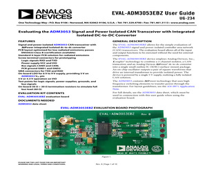
n Figure 4. Locate the power delivery circuit in close proximity to the ADM3053 device, to ensure that the VCC trace is as short as possible. The EVAL-ADM3053EBZ PCB has a power delivery circuit located at the bottom of the PCB with a short trace from the ADP667ARZ regulator output (U3) to VCC (Pin 8). This layout example minimizes the loop area in which high frequency current can flow. An increase in the loop area results in an increase in the emissions levels. EN55022 RADIATED EMISSIONS TEST RESULTS The EVAL-ADM3053EBZ evaluation board is tested and certified to pass EN55022 Class B with a 2.48 dB V/m margin. EN55022 certification documents for the EVAL-ADM3053EBZ evaluation board is available to users upon request from Analog Devices. Table 2 provides a summary of the results. All EN55022 radiated emissions tests are performed with the PCB schematic and layout as described in Figure 7 to Figure 13. The EVAL-ADM3053EBZ evaluation boards are configured and tested with 5.0 V power supplied to the
 10 Pages, 337 KB, Original
uide EVALUATION BOARD SCHEMATICS 15679-006 EVAL-ADM2795EEPBZ User Guide UG-1120 R2 T93_POT A B C 1 71K5 R4 2 200k R5 3 GND1 U3 R15 0 *DO NOT FIT 1 2 VDD1 3 + C20 C10 10F 4 DD IN OUT LBO LBI SET GND SHDN 0 R9 8 J5-3 7 6 100nF 10 F + 5 C12 C18 C19 10F 100nF ADP667ARZ GND1 GND1 R11 T93_POT A B C 1 240k R12 2 200k R13 3 GND2 U2 R10 0 *DO NOT FIT 1 2 VDD2 3 + C16 C13 10F 4 DD IN OUT LBO LBI SET GND SHDN R14 8 0 J2-3 7 6 C15 C17 5 100nF 10F + C14 10F 100nF GND2 GND2 Figure 7. Schematics of the EVAL-ADM2795EEPBZ Evaluation Board, Page 2 Rev. 0 | Page 9 of 12 15679-007 ADP667ARZ UG-1120 EVAL-ADM2795EEPBZ User Guide 15679-008 ASSEMBLY DRAWINGS AND BOARD LAYOUT 15679-009 Figure 8. EVAL-ADM2795EEPBZ Evaluation Board Silkscreen 15679-010 Figure 9. EVAL-ADM2795EEPBZ Evaluation Board Top Layer Figure 10. EVAL-ADM2795EEPBZ Evaluation Board Bottom Layer Rev. 0 | Page 10 of 12 EVAL-ADM2795EEPBZ User Guide UG-1120 ORDERING INFORMATION BILL OF MATERIALS Table 5. Qty 3 2 2 4 1 4 2 3 1 2 1 1 1 2 1 2 2 2
 12 Pages, 353 KB, Original
S FOR REFERENCE ONLY AND ARE NOT APPROPRIATE FOR USE IN DESIGN. 012407-A 8 4.00 (0.1574) 3.80 (0.1497) Figure 17. 8-Lead Standard Small Outline Package [SOIC_N] Narrow Body (R-8) Dimensions shown in millimeters and (inches) ORDERING GUIDE Model1 ADP667ANZ ADP667ARZ ADP667ARZ-REEL7 1 Temperature Range -40C to +85C -40C to +85C -40C to +85C Output Voltage (V) 5 V/Adjustable 5 V/Adjustable 5 V/Adjustable Package Option 8-Lead PDIP 8-Lead SOIC_N 8-Lead SOIC_N Package Description N-8 R-8 R-8 Z = RoHS Compliant Part. --8-- REV. A ADP667 REVISION HISTORY 2/14--Rev. 0 to Rev. A Updated Outline Dimensions ......................................................... 8 Changes to Ordering Guide ............................................................ 8 REV. A --9-- ADP667 NOTES --10-- REV. A ADP667 NOTES REV. A --11-- ADP667 NOTES (c)2014 Analog Devices, Inc. All rights reserved. Trademarks and registered trademarks are the property of their respective owners. D02015-0-2/14(A) --12-- REV. A
 12 Pages, 156 KB, Original
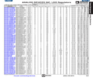
301ARZ-5 ADP3330ARTZ-2.5-R7 ADP3330ARTZ3.3-RL7 ADP3330ARTZ-5-RL7 ADP3331ARTZ-REEL7 ADP3303ARZ-3.3 ADP3303ARZ-5 ADP5050ACPZ-R7 ADP5052ACPZ-R7 ADM7170ACPZ-R7 ADM7150ARDZ-1.8 ADM7150ARDZ-2.8 ADM7150ARDZ-3.3 ADM7150ARDZ-5.0 ADM7151ARDZ-02 ADP3367ARZ ADP667ANZ ADP667ARZ ADP7112ACBZ-1.2-R7 ADP7112ACBZ-1.8-R7 ADP7112ACBZ-2.5-R7 ADP7112ACBZ-3.3-R7 ADP7118ACPZN-R7 ADP7118ARDZ-R7 ADP7118AUJZ-R7 ADP7118ACPZN-R7 ADP7112ACBZ-5.0-R7 ADP7102ARDZ-R7 ADP7102ARDZ-3.3-R7 ADP7104ARDZ-R7 ADP7104ACPZ-R7 ADP7105ARDZ ADP7105ARDZ-3.3 ADP7105ARDZ-5.0 ADP1720ARMZ-5-R7 ADP1720ARMZ-R7 ADP7142ACPZN-R7 ADP7142AUJZ-R7 ADP7142AUJZ-1.8-R7 ADP7142AUJZ-2.5-R7 ADP7142AUJZ-3.3-R7 ADP7142AUJZ-5.0-R7 ADP7142ACPZN-R7 ADP7142ARDZ-R7 Package TSOT-5 TSOT-5 TSOT-5 TSOT-5 TSOT-5 TSOT-5 TSOT-5 TSOT-5 LFCSP-16 TSOT-5 TSOT-5 TSOT-5 TSOT-5 LFCSP-8 LFCSP-8 MSOP-8 MSOP-8 MSOP-8 MSOP-8 MSOP-8 SOIC-8 SOIC-8 SOIC-8 SOIC-8 LFCSP-8 SOIC-8 SOT-223 SOT-223 SOT-223 SOT-223 SOT-223 LFCSP-8 LFCSP-8 SOT-223 SOT-223 SOT-223 SOT-223 SOT-223 SOT-223 LFCSP-8 SOI
 1 Pages, 516 KB, Original
0 Test points, black RH SMA connector Isolated Level 4 EMC and 24 V supply fault protected RS-485 transceiver 5 V fixed, adjustable voltage regulator Test points, red Vero TE Connectivity Analog Devices 20-2137 5-1814400-1 ADM2795EBRWZ Analog Devices Vero ADP667ARZ 20-313137 Rev. 0 | Page 15 of 16 UG-997 EVAL-ADM2795EEBZ User Guide NOTES ESD Caution ESD (electrostatic discharge) sensitive device. Charged devices and circuit boards can discharge without detection. Although this product features patented or proprietary protection circuitry, damage may occur on devices subjected to high energy ESD. Therefore, proper ESD precautions should be taken to avoid performance degradation or loss of functionality. Legal Terms and Conditions By using the evaluation board discussed herein (together with any tools, components documentation or support materials, the "Evaluation Board"), you are agreeing to be bound by the terms and conditions set forth below ("Agreement") unless you have purchased the Evaluation
 16 Pages, 487 KB, Original
SOT-223 12M8168 3.57 19M8716 2.50 2.80 5 0.2 150 12 8-SOIC 2.78 5 1 190 10 3-SOT-223 19M8721 2.57 3 0.15 110 5.5 16-WLCSP 63R1303 4.54 4.22 Mfg. Part No. AS1353-28-T AS1353-26-T AS1353-18-T AS1353-15-T QUAD OUTPUT AS1352-C0CF-T AS1352-7BC0-T Mfg. Part No. ADP667ARZ ADP1715ARMZ-R7 ADP3334ARZ ADP3331ARTZ-REEL7 ADP123AUJZ-R7 ADP3336ARMZ-REEL7 ADP323ACPZ-R7 ADP1720ARMZ-R7 ADP667ANZ Supply IO Max VDROP Voltage (mA) (mV) Max (V) 250 250 16.5 0.5 250 5.5 0.5 200 11 0.14 200 16 0.3 85 5.5 500 200 12 0.2 110 5.5 50 275 28 0.25 150 16.5 Price Each Package Stock No. 1-24 8-SOIC 59K2649 4.31 3.24 8-MSOP 28M3805 2.16 2.32 19M8718 2.20 2.43 8-SOIC 1.73 6-SOT-23 19M8717 1.71 5-TSOT 12T2968 1.08 0.98 96K2076 2.57 8-MSOP 2.39 16-LFCSP 18T2040 1.51 1.08 41M1920 1.29 1.43 8-MSOP 59K2648 4.51 8-DIP 3.40 ADP123-EVALZ 200 200 3 2.5 3 to 5.5 3 to 5.5 12-QFN 12-QFN 05R9377 05R9378 1.66 1.78 1.66 1.40 LOW DROPOUT VOLTAGE REGULATORS DROPOUT VOLTAGE: 390mV Mfg. Part No. SPX29302T5-L SPX29152T5-L Input Voltage Max (V) 16 16
 375 Pages, 58008 KB, Original